Volvo V40 Cross Country (2018 year). Instruction - part 18


  Index      Volvo     Volvo V40 Cross Country - instruction 2018 year in english


Search            


Content   ..  16  17  18  19   ..


Volvo V40 Cross Country (2018 year). Instruction - part 18


STARTING AND DRIVING

}}

* Option/accessory.

309

G021494

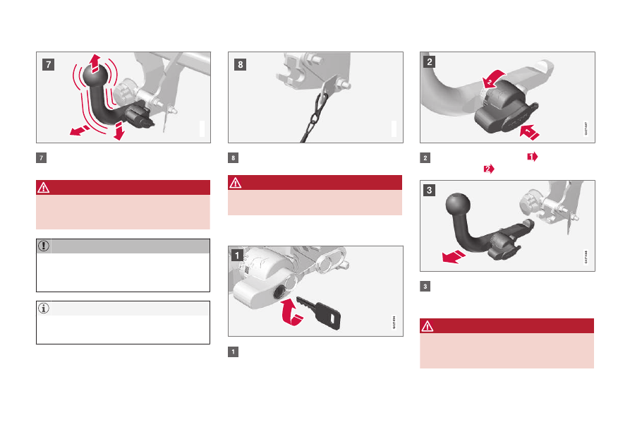
Check that the towball section is secure by
pulling it up, down and back.

WARNING

If the towball is not fitted correctly then it

must be detached and reattached in accord-

ance with the previous instructions.

IMPORTANT

Only grease in the ball for the towball hitch,
the remainder of the towbar must be clean
and dry.

NOTE

When a hitch with a vibration damper is used,
the towball must not be lubricated.

G021495

Safety cable.

WARNING

Take care to secure the trailer's safety cable

in the intended bracket.

Removal of removable towbar

Insert the key and turn it clockwise to the
unlocked position.

Push in the locking wheel 

 and turn it

anticlockwise 

 until you hear a click.

Turn the locking wheel down fully, until it
comes to a stop. Hold it in this position while
pulling the towball rearward and upward.

WARNING

Secure the detachable towbar safely if it is

stored in the car, see Detachable towbar

* -

storage (p. 306).

||

STARTING AND DRIVING

* Option/accessory.

310

Push the protective cover until it snaps tight.

Related information

Detachable towbar

* - storage (p. 306)

Detachable towbar

* - specifications (p. 307)

Driving with a trailer (p. 303)

Trailer Stability Assist - TSA

15

The trailer stability assist TSA (Trailer Stability
Assist) function is designed to stabilise the car
and trailer combination if it begins to snake.

TSA- the function is included in the stability sys-
tem (p. 186) ESC

16

.

Function

The snaking phenomenon can occur with any
car/trailer combination. Snaking normally occurs
at high speeds. But, there is a risk of it occurring
at lower speeds if the trailer is overloaded or the
load is improperly distributed, e.g. too far back.

In order for snaking to occur, there must be a
triggering factor, e.g.:

Car with trailer subjected to a sudden and
powerful side wind.

Car with trailer drives on an uneven road sur-
face or in a pothole.

Sweeping steering wheel movements.

Operation

If snaking has started, it could be difficult or even
impossible to suppress. This makes the car/
trailer combination difficult to control and there is
a risk that you could, for example, end up in the
wrong lane or leave the carriageway.

The trailer stability assist function continually
monitors car movements, particularly lateral
movements. If snaking is detected, the front
wheels are individually braked. This serves to sta-
bilise the car/trailer combination. This is often
enough to help the driver regain control of the
car.

If snaking is not eliminated the first time the TSA
system comes into action, the car/trailer combi-
nation is braked with all wheels and engine
power is reduced. Once snaking has been gradu-
ally suppressed and the car/trailer combination is
once again stable, the TSA system stops regulat-
ing and the driver once again has full control of
the car. For more information, see Electronic sta-
bility control (ESC) - general (p. 186).

Miscellaneous

Engagement of the TSA system may take place
at higher speeds.

NOTE

TSA function is switched off if the driver
selects 

Sport

 mode, see Electronic stability

control (ESC) - general (p. 186).

TSA may fail to engage if the driver uses severe
steering wheel movements to try to rectify the
snaking because in such a situation the TSA sys-

15

Included in the installation of Volvo genuine towbar.

16

(Electronic Stability Control) - Electronic stability control.

STARTING AND DRIVING

}}

311

tem cannot determine whether it is the trailer or
the driver that is causing the snaking.

The ESC

16

 symbol in the combined

instrument panel flashes when the TSA
system is working.

Related information

Electronic stability control (ESC) - general
(p. 186)

Towing

During towing, one vehicle is towed by another
vehicle using a tow rope.

Find out the statutory maximum speed limit for
towing before the towing begins.

1. Activate the car's hazard warning flashers.

2. Attach the tow rope in the towing eye.

3. Unlock the steering lock (p. 271) by inserting

the remote control key in the ignition switch
and giving a long press on the START/
STOP ENGINE button - key position II
(p. 81) is activated.

4. The remote control key must remain in the

ignition switch while the car is being towed.

5. Keep the towline taut when the towing vehi-

cle reduces speed by holding your foot gen-
tly pressed on the brake pedal - thereby
avoiding unnecessary jerking.

6. Be prepared to brake to stop.

WARNING

Check that the steering lock is unlocked
before towing.

The remote control key must be in key
position II - in position I all airbags are
deactivated.

Never remove the remote control key
from the ignition switch when the car is
being towed.

WARNING

The brake servo and power steering do not

work when the engine is switched off - the

brake pedal needs to be depressed

about 5 times more heavily and the steering is

considerably heavier than normal.

Manual gearbox

Prior to towing:

Move gear lever into neutral and release the
parking brake.

16

(Electronic Stability Control) - Electronic stability control.

||

STARTING AND DRIVING

* Option/accessory.

312

Automatic gearbox Geartronic

IMPORTANT

Note that the car must always be towed with
the wheels rolling forward.

Do not tow cars with automatic transmis-
sion at speeds higher than 80 km/h
(50 mph) or for distances in excess of 80
km.

Prior to towing:

Move the gear selector to position N and
release the parking brake.

Jump starting

Do not tow the car to bump start the engine. Use
a donor battery if the starter battery is discharged
and the engine does not start, see Jump starting
(p. 271).

IMPORTANT

The catalytic converter may be damaged dur-
ing attempts to tow-start the engine.

Related information

Hazard warning flashers (p. 99)

Towing eye (p. 312)

Towing eye

Use the towing eye for towing a vehicle. The
towing eye is screwed into a threaded socket
behind a cover on the right-hand side of the
bumper, front or rear.

Attaching the towing eye

1. Take out the towing eye that is stored in the

foam block under the cargo area floor.

2. The cover for the towing eye's attachment

point is available in two variants which must
be opened in the following way:

Open the rear bumper's recess using a
coin or similar inserted in the recess,
carefully turning it outwards. Then turn out
the cover completely and remove it.

The front bumper's recess has a marking
along one side or in a corner: Press the
marking with a finger and fold out the
opposite side/corner at the same time -
the cover turns around its axis and can
then be removed.

3. Screw the towing eye right in up to its flange.

Turn in the towing eye firmly e.g. using the
wheel wrench

*.

IMPORTANT

The towing eye is only designed for towing on
roads - not for pulling the car unstuck or out
of a ditch. Call a recovery service for recovery
assistance.

Removal

1. Unscrew and remove the towing eye after

use. Place the towing eye back in its position
in the foam block.

2. Refit the cover on the bumper.

STARTING AND DRIVING

313

Related information

Towing (p. 311)

Recovery (p. 313)

Recovery

Recovery means that the vehicle is transported
away by means of another vehicle.

Call a recovery service for recovery assistance.

The towing eye may be used to pull the car up
onto a recovery vehicle with a flatbed platform.
The car's position and ground clearance deter-
mine whether it is possible. If the slope of the
recovery vehicle's ramp is too steep, or if the
ground clearance under the car is inadequate,
then the car may be damaged if you try to pull it
up using the towing eye. Raise the car using the
recovery vehicle's lifting device if necessary.

IMPORTANT

Note that the car must always be transported
with the wheels rolling forward.

Related information

Towing (p. 311)

WHEELS AND TYRES

316

Tyres - maintenance

Amongst other things, the function of the tyres is
to carry load, provide grip on the road surface,
dampen vibration and protect the wheel from
wear.

Driving characteristics

Tyres greatly affect the car's driving characteris-
tics. The type of tyre, dimensions, tyre pressure
and speed rating are important for how the car
performs.

Tyre age

All tyres older than 6 years old should be
checked by an expert even if they seem undam-
aged. Tyres age and decompose, even if they are
hardly ever or never used. The function can
therefore be affected. This applies to all tyres that
are stored for future use. Examples of external
signs which indicate that the tyre is unsuitable for
use are cracks or discoloration.

New tyres

Tyres are perishable. After a few years they begin
to harden at the same time as the friction
capacity/characteristics gradually deteriorate. For
this reason, aim to get as fresh tyres as possible
when you replace them. This is especially impor-
tant with regard to winter tyres. The last four dig-
its in the sequence mean the week and year of
manufacture. This is the tyre's DOT marking
(Department of Transportation), and this is stated
with four digits, for example 1510. The tyre in the
figure was manufactured in week 15 of 2010.

Summer and winter wheels

When summer and winter wheels are changed
the wheels should be marked with which side of
the car they were mounted on, for example L for
left and R for right.

Wear and maintenance

Correct tyre pressure (p. 318) results in more
even wear. Driving style, tyre pressure, climate
and road condition affect how quickly your tyres
age and wear. To avoid differences in tread depth
and to prevent wear patterns (p. 318) arising, the
front and rear wheels can be switched with each
other. A suitable distance for the first change is
approx. 5000 km and then at 10000 km inter-
vals. Volvo recommends the an authorised Volvo
workshop is contacted for checking if you are
uncertain about tread depth. If significant differ-
ences in wear (> 1 mm difference in tread depth)
between tyres have already occurred, then the
least worn tyres must always be fitted on the rear.
Understeer is normally easier to correct than
oversteer, and leads to the car continuing for-
wards in a straight line rather than having the
rear end skidding to one side, resulting in possi-
ble complete loss of control over the car. This is
why it is important for the rear wheels never to
lose grip before the front wheels.

Wheels with tyres fitted must be stored lying
down or hanging up - never standing up.

WARNING

A damaged tyre may lead to loss of control

over the car.

WHEELS AND TYRES

317

Related information

Tyres - dimensions (p. 319)

Tyres - speed ratings (p. 320)

Tyres - direction of rotation (p. 317)

Tyres - direction of rotation

Tyres with a tread pattern which are designed to
only turn in one direction have the direction of
rotation marked with an arrow.

G021778

The arrow shows the tyre's direction of rotation.

The tyre must always rotate in the same direction
throughout its lifespan. Tyres should only be
switched between front and rear positions, never
between left and right-hand sides, or vice versa. If
the tyres are fitted incorrectly, the car's braking
characteristics and capacity to force rain and
slush out of the way are adversely affected. Tyres
with the greatest tread depth should always be
fitted to the rear of the car (to decrease the risk
of skidding).

NOTE

Make sure that both pairs of wheels have the
same type and dimension, and also the same
make.

Follow the recommended tyre pressure (p. 318)
specified in the tyre pressure table.

Related information

Tyres - dimensions (p. 319)

Tyres - speed ratings (p. 320)

Tyres - maintenance (p. 316)

Tyres - tread wear indicators (p. 318)

WHEELS AND TYRES

318

Tyres - tread wear indicators

Tread wear indicators show the status of the
tyre's tread depth.

G021829

Tread wear indicators.

A tread wear indicators is a narrow elevation
across the longitudinal grooves of the tyre's tread
pattern. On the side of the tyre are the letters
TWI (Tread Wear Indicator). When the tyre's tread
depth is down to 1.6 mm, the tread will be level in
height with the tread wear indicators. Change to
new tyres as soon as possible. Remember that
tyres with little tread depth provide very poor grip
in rain and snow.

Related information

Tyres - speed ratings (p. 320)

Tyres - air pressure (p. 318)

Tyres - direction of rotation (p. 317)

Tyres - air pressure

Tyres can have different air pressures which are
measured in bar.

Check the air pressure in the tyres

The air pressure for the tyres should be checked
every month and should be checked on cold
tyres. "Cold tyres" means the tyres are the same
temperature as the ambient temperature. After
several few kilometres of driving, the tyres warm
up and the pressure increases.

Inadequate tyre pressure increases fuel con-
sumption, shortens tyre lifespan and impairs the
car's driving characteristics. Driving on tyres with
tyre pressure that is too low could result in the
tyres overheating and being damaged. Tyre pres-
sure affects travelling comfort, road noise and
driving characteristics.

NOTE

Tyre pressure decreases over time, this is a
natural phenomenon. Tyre pressure also var-
ies depending on ambient temperature.

Tyre pressure label

G021830

The tyre pressure label on the driver's side door
pillar (between frame and rear door) shows which
pressure the tyres should have at different loads
and speed conditions. This is also specified in the
tyre pressure table.

Tyre pressure for the car's recommended tyre
dimension and information about ECO pressure
that results in improved fuel economy can be
found in the printed owner's manual.

NOTE

Temperature differences change the
tyre pressure.

Fuel economy, ECO pressure

When carrying a light load (max. 3 people) and at
speeds of up to 160 km/h (100 mph), the ECO

WHEELS AND TYRES

319

pressure can be selected to give the best possi-
ble fuel economy. If the best possible noise and
travelling comfort conditions are sought, the
lower comfort pressures are recommended
instead.

(See approved tyre pressures(p. 400).)

Related information

Tyres - speed ratings (p. 320)

Tyres - direction of rotation (p. 317)

Tyres - maintenance (p. 316)

Tyres - tread wear indicators (p. 318)

Tyres - approved tyre pressures (p. 400)

Wheel and wheel rim dimensions

Wheel and rim dimensions are designated in
accordance with the examples in the table
below.

The car has an approval for the complete vehicle.
This means that there are certain combinations
of wheels and tyres that are approved.

Wheels (rims) have a designation of dimensions,
for example: 7Jx16x50.

7

Rim width in inches

J

Rim flange profile

16 Rim diameter in inches

50 Off-set in mm (distance from wheel cen-

tre to wheel contact surface against the
hub)

Related information

Wheel nuts (p. 321)

Tyres - dimensions

The car's tyres have a certain dimension, see the
examples in the table below.

The dimensions are stated on all car tyres. Exam-
ple of designation:215/55R16 97W.

205 Tyre width (mm)

50

Ratio between tyre wall height and tyre
width (%)

R

Radial ply

17

Rim diameter in inches (")

93

Codes for the maximum permitted tyre
load, load index (p. 320) (LI)

W

Speed rating for maximum permitted
speed, speed rating (p. 320) (SS). (In
this case 270 km/h (168 mph)).

The car has an approval for the complete vehicle
with certain combinations of wheel rims and
tyres.

Related information

Tyres - air pressure (p. 318)

Tyres - direction of rotation (p. 317)

Tyres - tread wear indicators (p. 318)

WHEELS AND TYRES

320

Tyres - load index

Load index indicates a tyre's ability to carry a
certain load.

Each tyre has a certain capacity to carry a load, a
load index (LI). The car's weight determines the
load capacity required of the tyres.

Related information

Tyres - dimensions (p. 319)

Tyres - speed ratings (p. 320)

Tyres - air pressure (p. 318)

Tyres - tread wear indicators (p. 318)

Tyres - speed ratings

Each tyre can withstand a certain maximum
speed and therefore belongs to a particular
speed rating (SS - Speed Symbol).

Tyre speed class must at least correspond with
the car's top speed. The table below indicates the
maximum permitted speed that applies for each
speed rating (SS). The only exception to these
conditions is winter tyres (p. 321) (both those
with metal studs and those without), where a
lower speed rating may be used. If such a tyre is
chosen, the car must not be driven faster than
the speed rating of the tyre (for example, class Q
can be driven at a maximum of 160 km/h
(100 mph)). Traffic regulations determine how
fast a car can be driven, not the speed rating of
the tyres.

NOTE

The maximum permitted speed is specified in
the table.

Q

160 km/h (100 mph) (only used on win-
ter tyres)

T

190 km/h (118 mph)

H

210 km/h (130 mph)

V

240 km/h (149 mph)

W 270 km/h (168 mph)

Y

300 km/h (186 mph)

WARNING

The car must be fitted with tyres which have

the same or a higher load index (p. 320) (LI)

and speed rating (SS) than specified. If a tyre

with too low a load index or speed rating is

used, it may overheat.

Related information

Tyres - dimensions (p. 319)

Tyres - air pressure (p. 318)

Tyres - direction of rotation (p. 317)

WHEELS AND TYRES

}}

* Option/accessory.

321

Wheel nuts

Wheel nuts are used to fasten the wheels at the
hubs and are available in different versions.

Standard wheel nuts

Bulge acorn wheel nuts

Locking wheel nuts

Tightening torque

Type 1 wheel nut (steel wheel rim): 110
Nm

Type 2 wheel nut (aluminium wheel rim):
130 Nm

Type 3 Lockable wheel nut (steel/alumi-
nium wheel rim): 110 Nm

Only use rims that are tested and approved by
Volvo and which are Volvo genuine accessories.
Check the torque with a torque wrench.

Locking wheel nuts

*

Locking wheel nuts can be used on both alumi-
nium and steel rims. Under the cargo area floor
there is space for the sleeve for the lockable
wheel nuts.

Related information

Wheel and wheel rim dimensions (p. 319)

Winter tyres

Winter tyres are tyres that are adapted for winter
road conditions.

Winter tyres

Volvo recommends winter tyres with particular
dimensions. Tyre dimensions are dependent on
engine variant. When driving on winter tyres, the
correct type of tyres must be fitted to all four
wheels.

NOTE

Volvo recommends that you consult a Volvo
dealer about which wheel rim and tyre types
are most suitable.

Studded tyres

Studded winter tyres should be run in gently for
500-1000 km so the studs settle properly into
the tyres. This gives the tyre, and especially the
studs, a longer service life.

NOTE

The legal provisions for the use of studded
tyres vary from country to country.

Tread depth

Road conditions with ice, slush and low tempera-
tures place considerably higher demands on tyres
than summer conditions. Volvo therefore recom-

||

WHEELS AND TYRES

* Option/accessory.

322

mends not to drive on winter tyres that have a
tread depth of less than 4 mm.

Using snow chains

Snow chains may only be used on the front
wheels (also applies to all-wheel drive cars).
Never drive faster than 50 km/h (30 mph) with
snow chains. Avoid driving on bare ground as this
wears out both the snow chains and tyres.

WARNING

Use Volvo genuine snow chains or equivalent

chains designed for the car model, and tyre

and rim dimensions. In the event of uncer-

tainty Volvo recommends that you consult an

authorised Volvo workshop. The wrong snow

chains may cause serious damage to your car

and lead to an accident.

Related information

Changing wheels - removing wheels (p. 323)

Spare wheel*

A spare wheel (Temporary spare) is used to tem-
porarily replace a punctured normal wheel.

A spare wheel is only intended for use temporar-
ily and must be replaced by a normal wheel as
soon as possible. The car's handling may be
altered by the use of a spare wheel. The spare
wheel is smaller than the normal wheel. The car's
ground clearance is affected accordingly. Pay
attention to high kerbs and do not machine wash
the car. If the spare wheel is fitted on the front
axle, you cannot use snow chains at the same
time. On all-wheel drive cars the drive on the rear
axle can be disconnected. The spare wheel must
not be repaired. The correct tyre pressure for the
spare wheel is stated in the tyre pressure table,
Tyres - air pressure (p. 318).

IMPORTANT

Never drive faster than 80 km/h
(50 mph) with a spare wheel on the car.

The car must never be driven fitted with
more than one "Temporary Spare" wheel.

Related information

Changing wheels - removing wheels (p. 323)

Changing wheels - fitting (p. 325)

Changing wheels - taking out the spare
wheel

* (p. 323)

Jack

* (p. 327)

Warning triangle (p. 327)

Wheel nuts (p. 321)

WHEELS AND TYRES

}}

* Option/accessory.

323

Changing wheels - taking out the

spare wheel*

The spare wheel

* plus jack* and wheel wrench*

are stored under the floor in the cargo area.

1. Lift the rear edge of the luggage compart-

ment floor (or on models with a jointed lug-
gage compartment floor, take hold of the
luggage compartment floor handle, lift and
move the rear part of the floor forwards).

2. Lift out the storage compartment

* (only mod-

els with a jointed cargo area floor).

3. Lift out the lower floor (models with a jointed

luggage compartment floor only).

4. Undo the attaching screw and lift out the

foam block containing the jack and tools.

5. Take hold of the far end of the spare wheel,

then lift. Push the spare wheel forwards
slightly and lift it out of the storage compart-
ment.

Related information

Changing wheels - removing wheels (p. 323)

Changing wheels - fitting (p. 325)

Jack

* (p. 327)

Spare wheel

* (p. 322)

Warning triangle (p. 327)

Wheel nuts (p. 321)

Changing wheels - removing wheels

The car's wheels can be changed, e.g. to winter
wheels or a spare wheel.

Set up the warning triangle (p. 327) if a wheel
must be changed in a trafficked location. The car
and jack(p. 327)

* must be on a firm horizontal

surface.

1. Apply the parking brake, (p. 293) and

engage reverse gear, or position P if the car
has an automatic gearbox.

WARNING

Check that the jack is not damaged, that the

threads are thoroughly lubricated and that it is

free from dirt.

NOTE

Volvo recommends only using the jack

* that

belongs to the car model in question, which is
indicated on the jack's label.

The decal also indicates the jack's maximum
lift capacity at a specified lifting height.

2. Take out the wheel to be fitted as well as the

tools. If it is a spare wheel being fitted then
there is a package in its location containing
gloves and a plastic bag for the punctured
wheel.

||

WHEELS AND TYRES

* Option/accessory.

324

3. Place chocks in front of and behind the

wheels which will remain on the ground to
prevent them from rolling. Use heavy wooden
blocks or large stones for example.

4. Cars with steel rims have removable wheel

covers. Use the removal tool to hook in and
pull off any full-wheel wheel covers. Alterna-
tively, the wheel covers can be pulled away by
hand.

5. Screw together the towing eye with the

wheel wrench

* to the stop position.

Wheel wrench and towing eye.

IMPORTANT

The towing eye must be screwed into all
threads in the wheel wrench

*.

6. Remove the plastic caps from the wheel nuts

with the intended tool.

7. Loosen the wheel nuts ½-1 turn anticlock-

wise with the wheel wrench

*.

WHEELS AND TYRES

}}

* Option/accessory.

325

WARNING

Never position anything between the ground

and the jack, nor between the jack and the

car's jacking point.

8. There are two jacking points on each side of

the car. Wind up the jack

* so that the flange

in the bodywork ends up in the notch in the
head of the jack.

IMPORTANT

The ground under the jack must be firm,
smooth and level.

9. Lift the car so that the wheel is free. Remove

the wheel nuts and lift off the wheel.

WARNING

Never crawl under the car when it is raised on

the jack.
Passengers must leave the car when it is

raised on the jack. If a wheel must be

changed in a trafficked environment, passen-

gers must stand in a safe place.

Related information

Changing wheels - fitting (p. 325)

Changing wheels - taking out the spare
wheel

* (p. 323)

Spare wheel

* (p. 322)

Warning triangle (p. 327)

Wheel nuts (p. 321)

Changing wheels - fitting

It is important that the procedure for fitting the
wheel is carried out correctly.

Installation

WARNING

Never crawl under the car when it is raised on

the jack.
Passengers must leave the car when it is

raised on the jack. If a wheel must be

changed in a trafficked environment, passen-

gers must stand in a safe place.

1. Clean the contact surfaces between wheel

and hub.

2. Put on the wheel. Tighten the wheel nuts

thoroughly.

||

WHEELS AND TYRES

* Option/accessory.

326

3. Lower the car so that the wheels cannot

rotate.

4. Tighten the wheel nuts crosswise. It is impor-

tant that the wheel nuts are tightened with
the correct tightening torque. Check the tor-
que with a torque wrench.

5. Refit the plastic caps on the wheel nuts.

6.

Refit any full wheel covers.

NOTE

The wheel cover outlet for the valve must be
positioned over the valve on the wheel rim
during fitting.

Returning the tools to their places

After using the tools they must be returned to
their correct places in the foam block.

If the spare wheel has been used then the punc-
tured wheel can be placed in the plastic bag con-
tained in the package with the gloves. Return the
foam block to its place and press the retaining
screw down into the floor of the storage compart-
ment.

IMPORTANT

The tools and jack

* must be stored in the

intended location in the car's cargo area
when not in use.

NOTE

After a tyre has been inflated, always refit
the dust cap in order to avoid damage to
the valve from gravel, dirt, etc.

Only use plastic dust caps. Metal dust
caps can rust and become difficult to
unscrew.

When changing to another tyre
dimension

Contact an authorised Volvo workshop to update
the software each time the tyre dimension is
changed. A software download may be necessary
both when changing to larger and smaller dimen-
sions, and also when switching between summer
and winter wheels.

Related information

Changing wheels - taking out the spare
wheel

* (p. 323)

Changing wheels - removing wheels (p. 323)

Spare wheel

* (p. 322)

Warning triangle (p. 327)

Wheel nuts (p. 321)


Content   ..  16  17  18  19   ..