Volkswagen Golf / Golf GTI / Golf Variant. Manual - part 887


  Index      Volkswagen     Volkswagen Golf / Golf GTI / Golf Variant - service repair manual 2013 year


Search            copyright infringement  


Content   ..  885  886  887  888   ..


Volkswagen Golf / Golf GTI / Golf Variant. Manual - part 887


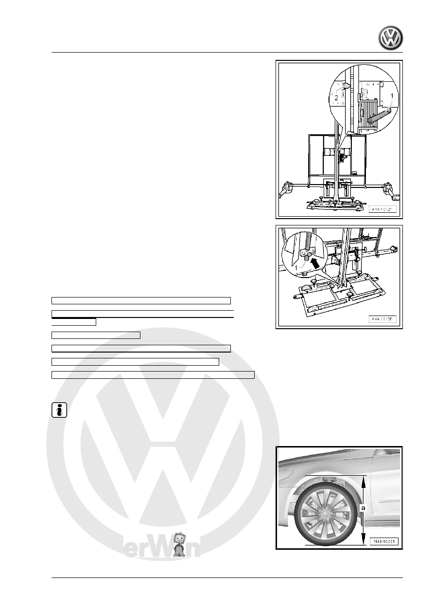
– Check specified height -2- one more time and adjust if neces‐

sary.

If the specified height was reached, then the measuring bar -1-

must be pushed slightly forward and secured with the locking bolt

-arrow-.
Perform Any Subsequent Work Using Vehicle Diagnostic Tester .
– Turn on the ignition.
– Select “Guided Fault Finding” on the Vehicle Diagnostic Test‐

er .

Body (Repair Groups 01, 27 and 50 through 97)

Electrical System (Repair Groups 01, 27 and 90

through 97)

01_OBD-Capable Systems

Driver Assistance Systems Front Camera -R242-

Driver Assistance System Camera, Functions

A5 - Calibrate the Control Module (Repair Group 44)

Follow the instructions on the screen to perform the calibration.

Note

Next, in guided fault finding, determine the height of the body.

– Enter the recorded ride heights.

7

Special Tools

Special tools and workshop

equipment required
♦ Wheel Alignment Comput‐

er - VAG1813F- or VW/Au‐

di approved wheel align‐

ment devices

♦ Brake Pedal Actuator -

VAG1869/2- .

♦ Insert Tool - 18mm -

T10179-

♦ Shock Absorber Set -

T10001-

♦ Insert Tool - 18mm - T10179-

♦ Torque Wrench 1332 40-200Nm - VAG1332-

♦ Torque Wrench 1332 Insert - Open Ring Wrench - 24mm -

VAG1332/9-

♦ Setting Device Basic Set - VAS6430/1-

♦ ACC Reflector Mirror - Audi - VAS6430/3-

48 – Steering

1

Steering Wheel

⇒ “1.1 Overview - Steering Wheel”, page 336
⇒ “1.2 Steering Wheel, Removing and Installing”, page 336

1.1

Overview - Steering Wheel

1 - Steering Column

❑ Removing and instal‐

ling. Refer to

⇒ “2.4 Steering Column,

Removing and Instal‐

ling”, page 340

 .

❑ The punch points

-arrows- on the steering

wheel and steering col‐

umn must be aligned

with each other when

positioning. Several

steering columns are

not equipped with a

punch point at the facto‐

ry. For these steering

columns, an appropriate

punch point must be set

before removing the

steering wheel. Refer to

⇒ “1.2 Steering Wheel,

Removing and Instal‐

ling”, page 336

 .

2 - Steering Wheel

❑ Removing and instal‐

ling. Refer to

⇒ “1.2 Steering Wheel,

Removing and Instal‐

ling”, page 336

 .

❑ There are different ver‐

sions. For allocation.

Refer to the Parts Cata‐

log.

❑ The punch points

-arrows- on the steering

wheel and steering col‐

umn must be aligned

with each other when

positioning. Several

steering columns are not equipped with a punch point at the factory. For these steering columns, an

appropriate punch point must be set before removing the steering wheel. Refer to

⇒ “1.2 Steering Wheel, Removing and Installing”, page 336

 .

3 - Bolt

❑ 30 Nm + 90°
❑ Replace after removal

1.2

Steering Wheel, Removing and Instal‐

ling

Special tools and workshop equipment required


Content   ..  885  886  887  888   ..