Volkswagen Golf / Golf GTI / Golf Variant. Manual - part 888


  Index      Volkswagen     Volkswagen Golf / Golf GTI / Golf Variant - service repair manual 2013 year


Search            copyright infringement  


Content   ..  886  887  888  889   ..


Volkswagen Golf / Golf GTI / Golf Variant. Manual - part 888


♦ Torque Wrench 1331 5-50Nm - VAG1331-
Removing

WARNING

Before performing work on the electrical system and removing

the steering wheel, the following conditions must be met:

♦ Disconnect the battery. Refer to ⇒  Electrical Equipment;

Rep. Gr.  27 ; Battery; Battery, Disconnecting and Con‐

necting .

♦ The wheels must be in the straight position.

The  airbag  system  may  fail  during  future  operation  if  these

warnings are not followed!

– Move the steering column to the center height position.
– Remove the airbag unit. Refer to ⇒  Body Interior; Rep. Gr. 

69 ; Overview - Driver Side Airbag .

– Bring wheels in the straight position.

Note

Removal and installation of steering wheel must take place in

center position (wheels in straight-ahead position).

– If equipped disconnect the steering wheel heating connector.
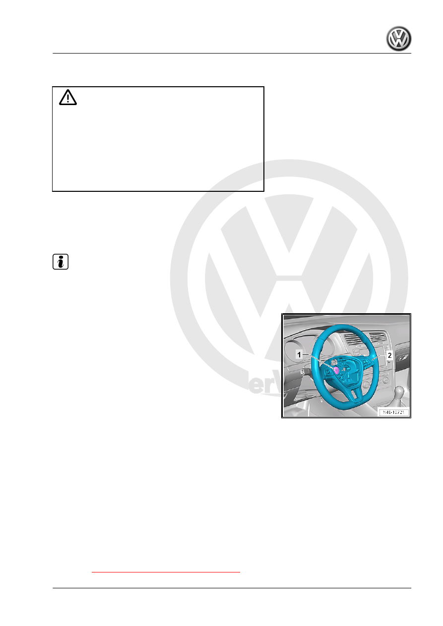
– Remove the bolt -1-.
– Check if the steering column is equipped with a punch point

on the steering column height marking.

– If that is not the case, then the steering wheel/steering column

position must be marked with a punch point on the steering

column.

– Remove the steering wheel -2- from the steering column.
Installing
Install in reverse order of removal. Note the following:
Make sure the wheels are in the straight-ahead position before

installing the steering wheel.
– When installing a removed steering wheel, ensure that the

markings on the steering column/steering wheel are aligned.

– When installing a new steering wheel (without a marking):

mount the steering wheel in its center position (the steering

wheel spokes must be horizontal and the wheels must be in

the straight-ahead position).

– Install steering wheel.
– Install the airbag unit. Refer to ⇒  Body Interior; Rep. Gr.  69 ;

Driver Side Airbag; Overview - Driver Side Airbag .

– Perform a road test.
– If steering wheel is crooked, remove it again and rotate it on

steering column splines.

Tightening Specifications
♦ Refer to 

⇒ “1.1 Overview - Steering Wheel”, page 336

2

Steering Column

⇒ “2.1 Overview - Steering Column”, page 338
⇒ “2.2 Steering Column, Checking for Damage”, page 339
⇒ “2.3 Steering Column, Handling and Transporting”, page 339
⇒ “2.4 Steering Column, Removing and Installing”, page 340
⇒ “2.5  Electronic Steering Column Lock Control Module J764 ,

Removing and Installing”, page 348

2.1

Overview - Steering Column

Note

Always replace self-locking nuts.

Always replace corroded bolts/nuts.

Always replace the bolts and nuts, which are tightened with an

additional tightening angle.

1 - Instrument Panel Central

Tube
2 - Shear Bolt

❑ Loosening and tighten‐

ing. Refer to

⇒ “2.5  Electronic Steer‐

ing Column Lock Con‐

trol Module J764 , Re‐

moving and Installing”,

page 348

3 - Right Retainer

❑ For knee airbag

4 - Electronic Steering Column

Lock Control Module - J764-

❑ For vehicles with “Key‐

less Access” keyless

locking and starting sys‐

tem

❑ Removing and instal‐

ling. Refer to

⇒ “2.5  Electronic Steer‐

ing Column Lock Con‐

trol Module J764 , Re‐

moving and Installing”,

page 348

5 - Bolt

❑ 20 Nm
❑ Follow the tightening se‐

quence. Refer to

⇒ page 346

❑ Replace after removal

6 - Left Retainer

❑ For knee airbag

7 - Bolt

❑ 20 Nm

❑ Replace after removal

8 - Bolt

❑ 20 Nm + 90°
❑ Replace after removal

9 - Steering Column

❑ Removing and installing. Refer to 

⇒ “2.4 Steering Column, Removing and Installing”, page 340

 .

❑ The steering column must be engaged on the instrument panel central tube bracket when installing

(assembly aid).

❑ There are different versions. Refer to the Parts Catalog.

2.2

Steering Column, Checking for Damage

Visual Check
– Check whether steering column parts show signs of damage.
Functional Check
– Check that the steering column turns easily without jerking.
– Check whether steering column can be easily adjusted later‐

ally and vertically.

2.3

Steering Column, Handling and Trans‐

porting

WARNING

♦ The correct handling of the steering column must always

be observed.

♦ Incorrect handling of steering column may cause damage

to steering column and therefore lead to a safety risk.

Correct Handling and Transport of Steering Column
♦ Transport the steering column with two hands.
♦ Hold the steering column by the upper outer steering column

tube and in the area of the upper universal joint.

Incorrect Handling of Steering Column
Transporting at the clamping lever leads to pre-damage to the

steering column.

Incorrect Handling of Steering Column with Safety Risk
The following handling techniques can lead to damage of the uni‐

versal joint bushings, the lower steering column bearing and the

steering column:
♦ Transporting steering column with one hand on joint shaft.
♦ Bending joints more than 90°.

2.4

Steering Column, Removing and Instal‐

ling

Special tools and workshop equipment required
♦ Torque Wrench 1331 5-50Nm - VAG1331-
♦ Torque Wrench 1332 40-200Nm - VAG1332-

Caution

This procedure contains mandatory replaceable parts. Refer

to component overview prior to starting procedure.

Mandatory Replacement Parts
♦ Bolts - Left Retainer to Steering Column
♦ Bolts - Right Retainer to Steering Column
♦ Shear Bolts - Steering Column to Electronic Steering Column

Lock Control Module

♦ Bolt - Steering Column to Steering Gear
Removing
The steering column is delivered only as a complete replacement

part. Service is not possible.


Content   ..  886  887  888  889   ..