Volkswagen Golf / Golf GTI / Golf Variant. Manual - part 886


  Index      Volkswagen     Volkswagen Golf / Golf GTI / Golf Variant - service repair manual 2013 year


Search            copyright infringement  


Content   ..  884  885  886  887   ..


Volkswagen Golf / Golf GTI / Golf Variant. Manual - part 886


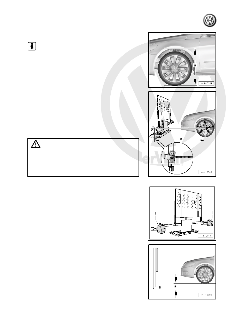
– Measure and record the height at all four wheels.

Note

The Setting Device Basic Set - VAS6430/1- must not be

moved on the calibration beam.

The alignment stand must be in the lowest level position for

the next step.

– Rotate the Setting Device Basic Set - VAS6430/1- upward just

enough so that the calibration beam is parallel to the center of

the measuring sensors on the front wheels, so that it is possi‐

ble to correctly measure the distance measuring unit -1-.

1 - Distance measuring unit with spring tape measure and

mounting pin

– Position the Setting Device Basic Set - VAS6430/1- at a dis‐

tance -a- of 1,500 mm ± 25 mm (59 ± 0.98 in) from the center

of the wheel hub on the front wheels to the beam on the Setting

Device Basic Set - VAS6430/1- .

Caution

♦ Distance -a- 1,500 mm ± 25 mm (59 ± 0.98 in) must be

measured on both side of the vehicle and then the Setting

Device Basic Set - VAS6430/1- must be aligned.

♦ Distance -a- must be the same on both sides of the vehi‐

cle.

– Mount the front wheel measuring sensors -1- to the Setting

Device Basic Set - VAS6430/1- .

– Determine the height value -a- between the Setting Device

Basic Set - VAS6430/1- contact area and the wheel contact

surface on the vehicle alignment platform. Enter it in the align‐

ment computer.

– Loosen the clamping bolt -arrow- and place the measuring bar

-1- on the floor.

– Turn the crank -1- to adjust the Calibration Board For Lane

Guard System - VAS6430/4- to the height specification -2- and

then make a note of it.

If the specified height was reached, then the measuring bar -1-

must be pushed slightly forward and secured with the locking bolt

-arrow-.

– Slide the Setting Device Basic Set - VAS6430/1- to the side

-arrows B-, until the display in the wheel alignment computer

is in the tolerance range.

– By gently turning the adjustment screws -2 and 3-, the Setting

Device Basic Set - VAS6430/1- is secured from rolling away.

– Turn the precision adjustment screw -1- until the display on

the wheel alignment computer is located within the tolerance

range.

– Level the bubble level -A- using the adjusting screw -1-.

– Level the bubble level -B- using the adjusting screws

-2 and 3-.

– Loosen the clamping bolt -arrow- and place the measuring bar

-1- on the floor.


Content   ..  884  885  886  887   ..