Volkswagen Golf / Golf GTI / Golf Variant. Manual - part 885


  Index      Volkswagen     Volkswagen Golf / Golf GTI / Golf Variant - service repair manual 2013 year


Search            copyright infringement  


Content   ..  883  884  885  886   ..


Volkswagen Golf / Golf GTI / Golf Variant. Manual - part 885


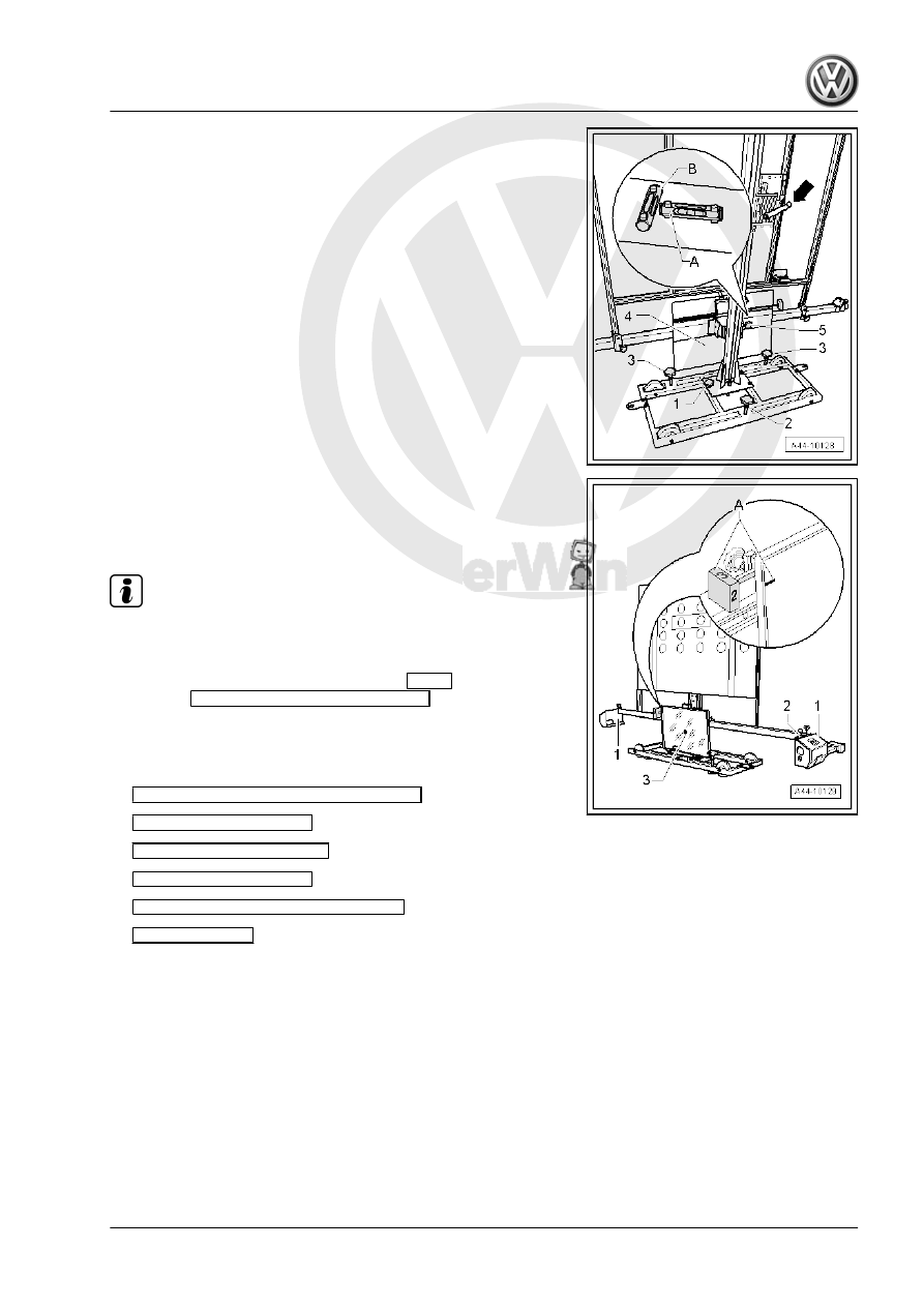
– Turn the precision adjustment screw -5- until the display on

the wheel alignment computer is located within the tolerance

range.

– Level the bubble levels -2- of the measurement sensor -1-.
– Using the laser beam -3- on the ACC Reflector Mirror - Audi -

VAS6430/3- , check whether the bubble level is level and the

laser beam is in the center of the sensor lens.

Note

If the laser beam does not meet the sensor lens, the ACC Re‐

flector Mirror - Audi - VAS6430/3- must be aligned again.

– On the Vehicle Diagnostic Tester , press 

GO TO

 and select the

function 

Function/Component Selection

.

Selection on the Vehicle Diagnostic Tester for the adjustment of

the Distance Regulation Control Module - J428- :
– Press the following buttons one after another on the screen:

Chassis (Repair Group 01; 40 - 49)

13 - Distance Control

01 - OBD-Capable System

13 - Distance Control

13 - Distance Control, Functions

13 - Calibrate

Follow the instructions on the screen to perform the adjustment.

Designation of the Distance Regulation Control Module - J428-

adjusting screws
1 - Adjusting screw 1
2 - Adjusting screw 2
3 - Must not be turned - functions only as a pivot point

WARNING

The ACC adjustment is only applied when “Output diagnostic

test complete” is displayed on the Vehicle Diagnostic Tester .

6

Driver Assistance Systems Front

Camera

⇒ “6.1 Driver Assistance Systems Front Camera, Calibrating”,

page 327

6.1

Driver Assistance Systems Front Cam‐

era, Calibrating

Special tools and workshop equipment required
♦ Setting Device Basic Set - VAS6430/1-
♦ Calibration Board For Lane Guard System - VAS6430/4-
♦ Wheel Alignment Computer
♦ Vehicle Diagnostic Tester

Note

If the camera can no longer recognize the lane markings due to

poor visibility, this could be caused by:

♦ The camera visual field is dirty or icy. If that is the problem, it

should be corrected.

♦ The camera view field in fogged over.
If there is a lot of dirt on the inside of the glass in the camera view

window, this must be cleaned off by hand. To do this, remove the

control module and the lens and clean the glass with washer fluid.

To remove the control module and lens. Refer to ⇒  Electrical

Equipment; Rep. Gr.  96 ; Driver Assistance Systems Front Cam‐

era; Driver Assistance Systems Front Camera, Removing and

Installing .
The calibration must be correct for the Driver Assistance Systems

Front Camera - R242- to function correctly.
The Driver Assistance Systems Front Camera - R242- must be

calibrated again for the following reasons:
♦ “No or incorrect basic setting/adaptation” is stored in the event

memory.

♦ The Driver Assistance Systems Front Camera - R242- was

replaced.

♦ The windshield was replaced or removed.
♦ The rear axle toe was adjusted.
♦ Work was performed on the chassis which influences the body

height.

♦ The vehicle level sensor was readapted on vehicles with

damping regulation.

Note

Before calibrating the driver assistance systems front camera,

check the Diagnostic Trouble Code (DTC) memory and cor‐

rect any faults.

The driver assistance systems front camera may only be cali‐

brated using alignment equipment approved by VW/Audi.

Only the Setting Device Basic Set - VAS6430/1- may be used

to calibrate the driver assistance systems front camera.

Note

The Driver Assistance Systems Front Camera - R242- must fit

correctly in the retainer.

The camera viewing range must be clean and unobstructed.

Before driving the vehicle onto the vehicle alignment platform,

make sure there is sufficient space between the center of the

wheel hub on the front wheels and the Setting Device Basic

Set - VAS6430/1- .

The distance between the Setting Device Basic Set -

VAS6430/1- and the center of the wheel hub on the front

wheels must be 1,500 mm ± 25 mm (59 ± 0.98 in).

If there is not sufficient space, drive the vehicle backward onto

the alignment stand in order to use the corresponding space.

The calibration board must be positioned in the center of the

setting device.

Before beginning the calibration, check the DTC memory. If

necessary, erase any existing entries.

– Follow the test requirements for an axle alignment. Refer to

⇒ “3.2 Test Prerequisites”, page 296

 .

– Drive the vehicle onto the vehicle alignment platform.
– Connect the battery charger. Refer to ⇒  Electrical Equipment

General Information; Rep. Gr.  27 ; Battery, Charging .

– Connect Vehicle Diagnostic Tester (Guide the diagnostic ca‐

ble through the open window.)

Note

During the calibration procedure, make sure all the vehicle doors

remain closed and the vehicle exterior lamps are switched off.

– Position the front wheels so they are straight.
– Select calibrating the driver assistance systems front camera

in the wheel alignment computer.

– Install the quick-action clamps on all four wheels.
– Install the measuring sensors on the wheels.
– Perform a wheel run-out compensation and the rear wheels.
– Bounce the vehicle.


Content   ..  883  884  885  886   ..