Volkswagen Golf / Golf GTI / Golf Variant. Manual - part 773


  Index      Volkswagen     Volkswagen Golf / Golf GTI / Golf Variant - service repair manual 2013 year


Search            copyright infringement  


Content   ..  771  772  773  774   ..


Volkswagen Golf / Golf GTI / Golf Variant. Manual - part 773


Continuation for All Vehicles
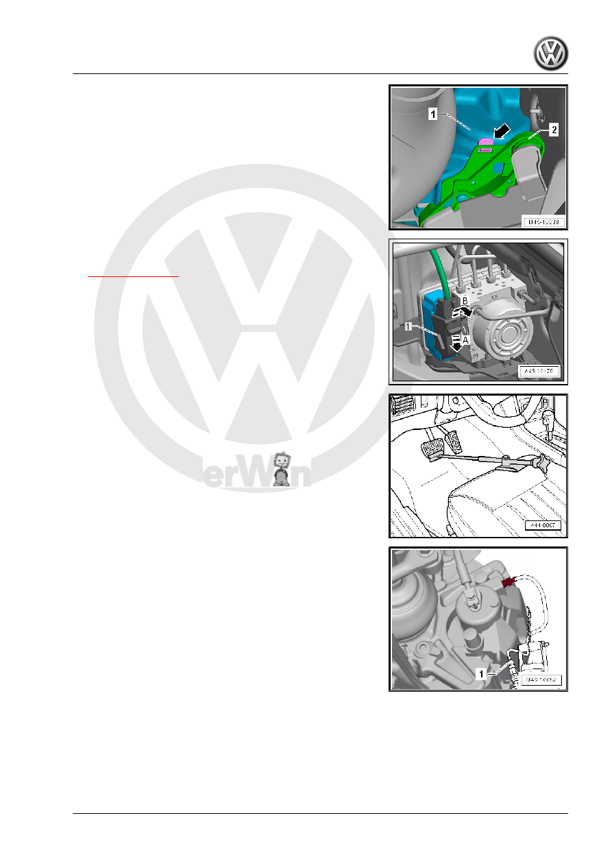
– If equipped, remove the heat shield -1-.

– Unclip the heat shield -1- from the bracket -2- -arrow-.
– On vehicles with heat shield, remove heat shield -item 14-

⇒ Item 14 (page 16)

 .

– Unclip the wire routing.
– Push the lock washer downward in the direction of -arrow A-.
– Release the locking mechanism in the direction of -arrow B-.
– Remove the connector -1-.

– Install the Brake Pedal Actuator - VAG1869/2- .

– Attach the bleeder bottle bleed hose -1- to the left front brake

caliper bleed valve.

– Open the bleed valve.

– Attach the bleeder bottle bleed hose -1- to the left rear brake

caliper bleed valve.

– Open the bleed valve.
– Push the brake pedal with the Brake Pedal Actuator -

VAG1869/2- at least 60 mm.

– Close left front and left rear bleeder valves.
– Do not remove the Brake Pedal Actuator - VAG1869/2- .
– Place a lint-free cloth under the ABS Control Module - J104-

and the ABS Hydraulic Unit - N55- .

Note

Make sure no brake fluid gets onto contacts.

– Remove the cover from the bulkhead and unclip the brake line.

– Label both brake lines -5 and 6-.
– Remove the brake lines -5 and 6- from the ABS Hydraulic Unit

- N55- .

– Seal off the brake lines and the threaded holes right away with

the plugs from repair kit 1H0 698 311 A.

– Mark, unfasten and plug the remaining brake lines (brake cal‐

ipers).

– Pull the ABS Hydraulic Unit - N55- with the ABS Control Mod‐

ule - J104- upward from the shock absorber -arrow-.

– Place the ABS Hydraulic Unit - N55- with the ABS Control

Module - J104- at the bottom of the engine compartment.

Caution

Set aside the ABS Hydraulic Unit - N55- with the ABS Control

Module - J104- so that it cannot fall down.

– Raise the vehicle.

For Vehicles with a Parking/Auxiliary Heater
– Remove the bracket in the vehicle from the ABS Hydraulic Unit

- N55- -arrows-.

Continuation for All Vehicles
– Guide the ABS Hydraulic Unit - N55- from the vehicle.
Installing
Install in reverse order of removal. Note the following:

Note

Remove the plugs on the new ABS Hydraulic Unit - N55- only

when installing the brake line.

Brake fluid will leak out if the plugs are removed too early from

the ABS Hydraulic Unit - N55- . The system will then not have

sufficient brake fluid and will not adequately bled.

Pay attention when installing the ABS Hydraulic Unit - N55-

that the rubber bushings are not pushed out of the console.

– Before assembling the holder for the ABS Hydraulic Unit -

N55- in the bracket, spray the rubber bushings with Silicone

Lubricant Spray - D 007 000 A2- .

– Install the brake lines carefully with the Torque Wrench - As‐

sembly Tool - VAG1410/8- .

Brake Line Tightening Sequence
– Remove the Brake Pedal Actuator - VAG1869/2- .
– Bleed the brake system. Refer to

⇒ “6 Hydraulic System”, page 132

 .

– Enter radio code.
– Code the ABS Control Module - J104- using the Vehicle Di‐

agnostic Tester .

A Steering Angle Sensor - G85- , Transverse Acceleration Sensor

- G200- , Longitudinal Acceleration Sensor - G251- and Brake

Pressure Sensor 1 - G201- basic setting must be done.
Tightening Specifications

Special Tool Assembly for Tightening the Brake Lines
♦ Refer to

⇒ “3.1 Overview - Control Module and Hydraulic Unit”,

page 15

♦ Refer to ⇒  Engine Mechanical, Fuel Injection and Ignition;

Rep. Gr.  26 ; Exhaust Pipes/Mufflers; Overview - Muffler .

♦ Refer to ⇒  Body Exterior; Rep. Gr.  66 ; Noise Insulation;

Overview - Noise Insulation .

♦ Refer to ⇒  Engine Mechanical, Fuel Injection and Ignition;

Rep. Gr.  26 ; Exhaust Pipes/Mufflers; Muffler, Removing and

Installing .

♦ Refer to ⇒  Engine Mechanical, Fuel Injection and Ignition;

Rep. Gr.  10 ; Subframe Mount; Overview - Subframe Mount .

♦ Refer to ⇒  Engine Mechanical, Fuel Injection and Ignition;

Rep. Gr.  10 ; Engine Cover; Engine Cover, Removing and

Installing .

♦ Front bleeder valve. Refer to

⇒ “1.1 Overview - Front Brake Caliper”, page 97

 .

♦ Rear bleeder valves. Refer to

⇒ “2.1 Overview - Rear Brake Caliper”, page 100

3.2.3

ABS Control Module and ABS Hydraulic

Unit, Removing and Installing

Special tools and workshop equipment required
♦ Torque Wrench 1331 5-50Nm - VAG1331-
♦ Open Ring Spanner Insert - AF 11mm - VAG1410/6-
♦ Torque Wrench - Universal Joint - VAG1410/7-
♦ Mini Torque Wrench - VAS6854-
♦ Brake Pedal Actuator - VAG1869/2- .
♦ Torque Wrench - Assembly Tool - VAG1410/8-
Plug assembly part number 5Q0 698 311
1 - M10 plug
2 - M12 plug
Removing
Component location:


Content   ..  771  772  773  774   ..