Volkswagen Golf / Golf GTI / Golf Variant. Manual - part 772


  Index      Volkswagen     Volkswagen Golf / Golf GTI / Golf Variant - service repair manual 2013 year


Search            copyright infringement  


Content   ..  770  771  772  773   ..


Volkswagen Golf / Golf GTI / Golf Variant. Manual - part 772


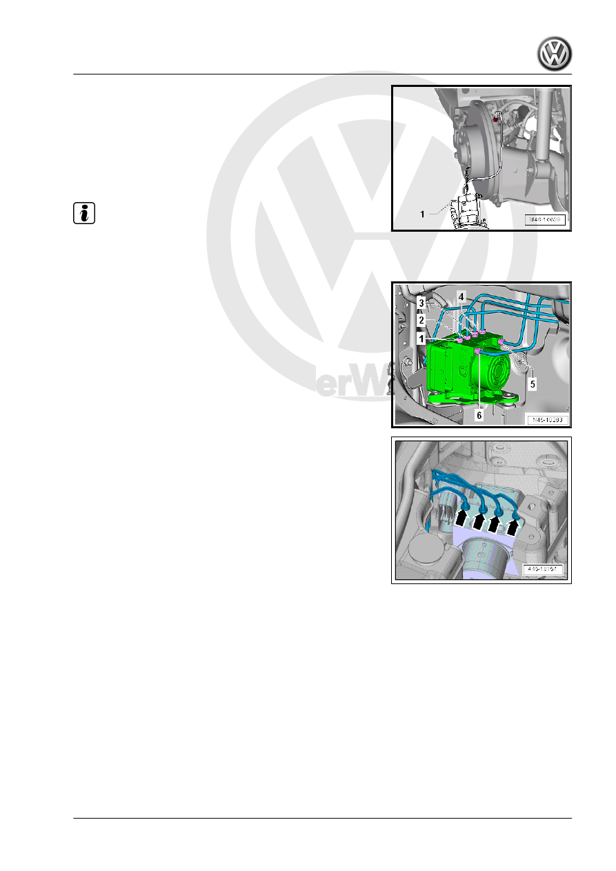
– Attach the bleeder bottle bleed hose -1- to the left rear brake

caliper bleed valve.

– Open the bleed valve.
– Push the brake pedal with the Brake Pedal Actuator -

VAG1869/2- at least 60 mm.

– Close left front and left rear bleeder valves.
– Do not remove the Brake Pedal Actuator - VAG1869/2- .

Note

Make sure no brake fluid gets onto contacts.

– Remove the cover from the bulkhead and unclip the brake line.

– Label both brake lines -5 and 6-.
– Remove the brake lines -5 and 6- from the ABS Hydraulic Unit

- N55- .

– Close brake lines and open connections using Sealing Plugs

from the Repair Kit - 1H0 698 311 A- or with suitable plugs

from the Engine Bung Set - VAS6122- .

– Label the remaining brake lines (brake caliper) -arrows- and

remove.

– Close brake lines and open connections using Sealing Plugs

from the Repair Kit - 1H0 698 311 A- or with suitable plugs

from the Engine Bung Set - VAS6122- .

– Pull the ABS Control Module - J104- with the ABS Hydraulic

Unit - N55- upward from the shock absorber -arrow-.

Installing
Install in reverse order of removal. Note the following:

Note

Remove the plugs on the new ABS Hydraulic Unit - N55- only

when installing the brake line.

Brake fluid will leak out if the plugs are removed too early from

the ABS Hydraulic Unit - N55- . The system will then not have

sufficient brake fluid and will not adequately bled.

Pay attention when installing the ABS Hydraulic Unit - N55-

that the rubber bushings are not pushed out of the console.

– Before assembling the holder for the ABS Hydraulic Unit -

N55- in the bracket, spray the rubber bushings with Silicone

Lubricant Spray - D 007 000 A2- .

– Install the brake lines carefully with the Torque Wrench - As‐

sembly Tool - VAG1410/8- .

Tightening Sequence
– Remove the Brake Pedal Actuator - VAG1869/2- .
– Bleed the brake system. Refer to

⇒ “6 Hydraulic System”, page 132

 .

– Enter radio code.
– Code ABS Control Module - J104- using the Vehicle Diagnos‐

tic Tester in "Guided Fault Finding".

A Steering Angle Sensor - G85- , Transverse Acceleration Sensor

- G200- , Longitudinal Acceleration Sensor - G251- and Brake

Pressure Sensor 1 - G201- basic setting must be done.
Tightening Specifications

Special Tool Assembly for Tightening the Brake Lines
♦ Refer to

⇒ “3.1 Overview - Control Module and Hydraulic Unit”,

page 15

♦ Refer to ⇒  Engine Mechanical, Fuel Injection and Ignition;

Rep. Gr.  10 ; Engine Cover; Engine Cover, Removing and

Installing .

♦ Refer to ⇒  Engine Mechanical, Fuel Injection and Ignition;

Rep. Gr.  26 ; Exhaust Pipes/Mufflers; Overview - Muffler .

♦ Refer to 

⇒ “1.1 Overview - Front Brake Caliper”, page 97

♦ Refer to 

⇒ “2.1 Overview - Rear Brake Caliper”, page 100

3.2.2

ABS Control Module and ABS Hydraulic

Unit, Removing and Installing

Special tools and workshop equipment required
♦ Torque Wrench 1331 5-50Nm - VAG1331-
♦ Open Ring Spanner Insert - AF 11mm - VAG1410/6-
♦ Torque Wrench - Universal Joint - VAG1410/7-
♦ Mini Torque Wrench - VAS6854-
♦ Brake Pedal Actuator - VAG1869/2- .
♦ Torque Wrench - Assembly Tool - VAG1410/8-
Plugs 5Q0 698 311
1 - M10 Plug
2 - M12 Plug
Installed Component Location

The ABS Control Module - J104- is attached to the ABS Hydraulic

Unit - N55- -1- and is located inside the engine compartment on

the right side.
Removing

WARNING

Do  not  bend  the  brake  lines  near  the  ABS  Hydraulic  Unit  -

N55- !

– Read and note the present control module coding.
– If the vehicle has a coded radio, get the radio code from the

customer before beginning.

– Disconnect the battery. Refer to ⇒  Electrical Equipment; Rep.

Gr.  27 ; Battery; Battery, Disconnecting and Connecting .

– Remove the engine cover. Refer to ⇒  Engine Mechanical,

Fuel Injection and Ignition; Rep. Gr.  10 ; Engine Cover; Engine

Cover, Removing and Installing .

Diesel Engine with Particulate Filter
– Remove the noise insulation. Refer to ⇒  Body Exterior; Rep.

Gr.  66 ; Noise Insulation; Overview - Noise Insulation .

– Remove the drive axle heat shield if equipped -arrows-. Refer

to ⇒  Suspension, Wheels, Steering; Rep. Gr.  40 ; Drive Axle;

Drive Axle Heat Shield, Removing and Installing .

– Remove the front exhaust pipe. Refer to ⇒  Rep. Gr.  26 ; Ex‐

haust Pipes/Mufflers; Front Exhaust Pipe, Removing and In‐

stalling .

– Disconnect the connector -1-.
– Loosen the clamping sleeve -2- and slide it toward the rear.

– Remove the bolts -1-.
– Loosen the bolt -2- and remove the clamp.
– Remove the front exhaust pipe.

For Vehicles with a Parking/Auxiliary Heater
– Remove the front exhaust pipe. Refer to ⇒  Engine Mechani‐

cal, Fuel Injection and Ignition; Rep. Gr.  26 ; Exhaust Pipes/

Mufflers; Muffler, Removing and Installing .

– Remove both nuts -arrows- from the coolant line bracket -1-

on the longitudinal member and the bracket.

– Pull the bracket from the pins and pull the coolant line as far

downward as possible.


Content   ..  770  771  772  773   ..