Volkswagen Golf / Golf GTI / Golf Variant. Manual - part 771
3
Control Module and Hydraulic Unit
⇒ “3.1 Overview - Control Module and Hydraulic Unit”,
page 15
⇒ “3.2 ABS Control Module J104 / ABS Hydraulic Unit N55 , Re‐
moving and Installing”, page 17
⇒ “3.3 Control Module, Separating from Hydraulic Unit”,
page 31
⇒ “3.4 Control Module, Attaching to Hydraulic Unit”, page 32
⇒ “3.5 Brake Lines, Attaching to Hydraulic Unit”, page 33
3.1
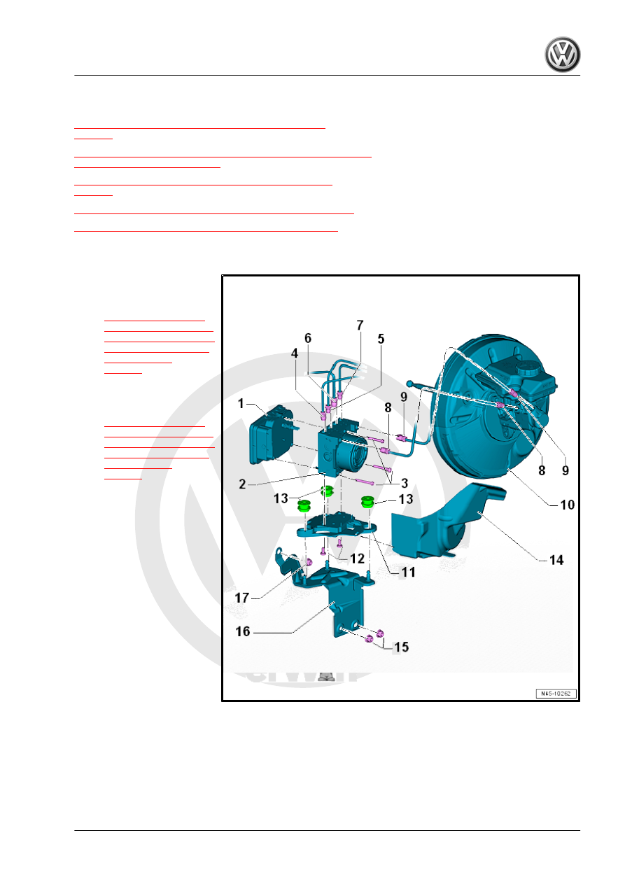
Overview - Control Module and Hydraulic Unit
1 - ABS Control Module - J104-
❑ Removing and instal‐
ling. Refer to
.
2 - ABS Hydraulic Unit - N55-
❑ Removing and instal‐
ling. Refer to
.
3 - TORX
®
Bolt
❑ 1. Step: Preliminary
tightening specification
1 Nm to 1.5 Nm (to in‐
stall the seal)
❑ 2. Step: final tightening
specification: 2.5 Nm
❑ Install the new TORX
®
bolt in two steps switch‐
ing back and forth.
4 - Brake Line
❑ 14 Nm
❑ Identification: 5.25 mm
diameter and tube fitting
with a M12 x 1 thread
❑ To the right rear brake
caliper
5 - Brake Line
❑ 14 Nm
❑ Identification: 5.25 mm diameter and tube fitting with a M10 x 1 thread
❑ To the left front brake caliper
6 - Brake Line
❑ 14 Nm
❑ To the right front brake caliper