Volkswagen Golf / Golf GTI / Golf Variant. Manual - part 774


  Index      Volkswagen     Volkswagen Golf / Golf GTI / Golf Variant - service repair manual 2013 year


Search            copyright infringement  


Content   ..  772  773  774  775   ..


Volkswagen Golf / Golf GTI / Golf Variant. Manual - part 774


The control module is bolted to the hydraulic unit -1- and is located

at right in the engine compartment.

WARNING

Do  not  bend  the  brake  lines  near  the  ABS  Hydraulic  Unit  -

N55- !

– Read and note the present control module coding.
– If the vehicle has a coded radio, get the radio code from the

customer before beginning.

– Disconnect the battery. Refer to ⇒  Electrical Equipment; Rep.

Gr.  27 ; Battery; Battery, Disconnecting and Connecting .

– Remove the engine cover.
– Remove the noise insulation. Refer to ⇒  Body Exterior; Rep.

Gr.  66 ; Noise Insulation; Overview - Noise Insulation .

– Remove the front exhaust pipe. Refer to ⇒  Rep. Gr.  26 ; Ex‐

haust Pipes/Mufflers; Front Exhaust Pipe, Removing and In‐

stalling .

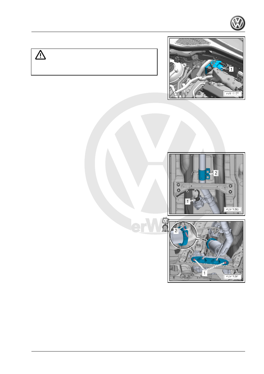
– Disconnect the connector -1-.
– Loosen the clamping sleeve -2- and slide it toward the rear.

– Remove the bolts -1-.
– Loosen the bolt -2- and the clamp.
– Remove the front exhaust pipe.
– Remove the right driveshaft. Refer to ⇒  Suspension, Wheels,

Steering; Rep. Gr.  40 ; Driveshaft; Driveshaft, Removing and

Installing

– Pivot the suspension strut to the rear and lock.
– On vehicles with heat shield, remove heat shield.
– Unclip the wire routing.

– Press the securing clip down -arrow A-.

– Disconnect the connector -arrow B-.
– Remove the connector -1-.

– Install the Brake Pedal Actuator - VAG1869/2- .

– Attach the bleeder bottle bleed hose -1- to the left front brake

caliper bleed valve.

– Open the bleed valve.

– Attach the bleeder bottle bleed hose -1- to the left rear brake

caliper bleed valve.

– Open the bleed valve.
– Push the brake pedal with the Brake Pedal Actuator -

VAG1869/2- at least 60 mm.

– Close left front and left rear bleeder valves.
– Do not remove the Brake Pedal Actuator - VAG1869/2- .
– Place sufficient lint-free cloths under the control module and

hydraulic unit.

Note

Make sure that brake fluid does not come in contact with the ter‐

minals.

– Remove the cover from the bulkhead and unclip the brake line.
– First, mark both brake lines from master cylinder and remove

from the hydraulic unit.

– Seal the threaded holes immediately with plugs from the as‐

sembly part set part number 5Q0 698 311.

– Mark, remaining brake lines (brake calipers), unfasten and

plug the threaded holes.

– Lift the hydraulic unit with control module up and out of the

dampers -arrow-.

– Place the hydraulic unit with the control module carefully below

in the engine compartment.

Caution

Set aside the ABS Hydraulic Unit - N55- with the ABS Control

Module - J104- so that it cannot fall down.

– Raise the vehicle.

– Remove the bracket in the vehicle from the hydraulic unit

-arrows-.

– Pivot the suspension strut -1- to the side and toward the rear.

Lock it in this position with a wooden block -2-.

– Carefully guide the hydraulic unit with the control module

downward.

– Carefully place the hydraulic unit with the control module at

the bottom of the engine compartment.

Note

Position the ABS Hydraulic Unit - N55- with the ABS Control Mod‐

ule - J104- so that it cannot fall down.

– Raise the vehicle.

– Guide out the hydraulic unit -3- out of the vehicle through the

wheel housing.

Installing

Note

Do not remove sealing plugs at new hydraulic unit until the

corresponding brake line is about to be installed.

If the sealing plugs are removed too early, brake fluid can es‐

cape and unit may not be sufficiently filled or adequately bled.

When installing the hydraulic unit, make sure the damper rub‐

ber is not pushed out of the console.

– Before assembling the holder for the ABS Hydraulic Unit -

N55- in the bracket, spray the rubber bushings with Silicone

Lubricant Spray - D 007 000 A2- .

– Install the brake lines carefully with the Torque Wrench - As‐

sembly Tool - VAG1410/8- .

– Install in reverse order of removal.

Brake Line Tightening Sequence
– Remove the Brake Pedal Actuator - VAG1869/2- .
– Bleed the brake system. Refer to

⇒ “6.2 Hydraulic System, Standard Bleeding”, page 132

 .

– Enter radio code.
– Code the ABS Control Module - J104- using the Vehicle Di‐

agnostic Tester .

A Steering Angle Sensor - G85- , Transverse Acceleration Sensor

- G200- , Longitudinal Acceleration Sensor - G251- and Brake

Pressure Sensor 1 - G201- basic setting must be done.
Tightening Specifications


Content   ..  772  773  774  775   ..