Volkswagen Golf / Golf GTI / Golf Variant. Manual - part 752


  Index      Volkswagen     Volkswagen Golf / Golf GTI / Golf Variant - service repair manual 2013 year


Search            copyright infringement  


Content   ..  750  751  752  753   ..


Volkswagen Golf / Golf GTI / Golf Variant. Manual - part 752


– Release and remove the breather line -2-. Disconnect the

connector couplings. Refer to

⇒ “4.1 Connector Couplings, Disconnecting”, page 62

 .

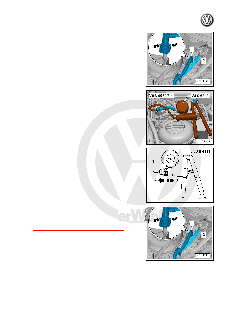
– Connect the -VAS6213- to line leading to the EVAP Canister

Purge Regulator Valve 1 - N80- using the -VAS6550/3-1- and

a commercially available hose.

– Set the slide ring -1- on the -VAS6213- in position -A- for “vac‐

uum”.

– Press the -VAS6213- several times. A vacuum must form.
If No Vacuum Forms:
– Check the line to the EVAP Canister Purge Regulator Valve 1

- N80- for leaks and damage.

If no Malfunction was Detected:
EVAP Canister Purge Regulator Valve 1 - N80- is not OK.

If a Vacuum Forms:
EVAP Canister Purge Regulator Valve 1 - N80- is OK:
– Release and remove the breather line -2-. Disconnect the

connector couplings. Refer to

⇒ “4.1 Connector Couplings, Disconnecting”, page 62

 .

– Connect the - VAS6213- with the -VAS6550/3-2- to the EVAP

canister line.

– Set the slide ring -1- on the -VAS6213- in position -A- for “vac‐

uum”.

– Press the -VAS6213- several times. No vacuum should be

built up.

If a Vacuum Forms:
– Remove the right rear wheel housing liner. Refer to ⇒  Body

Exterior; Rep. Gr.  66 ; Wheel Housing Liner; Overview - Rear

Wheel Housing Liner .

– Remove the cap -4- from the connection -1-.
– Check the vent connection -A- on the EVAP canister for con‐

tamination and clean it if necessary.

– Repeat the test.
If no Vacuum Forms:

– Remove the breather lines -2- at the connection -T- from the

EVAP canister. Disconnect the connector couplings. Refer to

⇒ “4.1 Connector Couplings, Disconnecting”, page 62

 .

– Seal the connection -3- using suitable service equipment.

– Seal the connection -A- on the EVAP canister -2- with a suit‐

able plug from the -VAS6122- -1-.

– Press the -VAS6213- several times. A vacuum must form.

If no vacuum forms:
– Remove the breather lines -2- at the connection -M- from the

EVAP canister -1-. Disconnect the connector couplings. Refer

to 

⇒ “4.1 Connector Couplings, Disconnecting”, page 62

 .

– Connect the -VAS6213- to the connection -M- on the EVAP

canister -1- using a commercially available hose -3-.

• Connection -2- is sealed using suitable materials.
• Connection -A- is sealed with a plug from the -VAS6122- .

Refer to 

⇒ page 75

 .

– Press the -VAS6213- several times. A vacuum must form.

If a Vacuum Forms:
– Check the line between the separating point -2- in the engine

compartment and the connection -M- on the EVAP canister,

replacing if necessary.

If no Vacuum Forms:
– Replace the EVAP canister. Refer to

⇒ “6.3.1 EVAP Canister, Removing and Installing, with Fuel

Tank Leak Detection”, page 70

 .

If Vacuum Builds up and the Line is OK:
– Check the line. Refer -item 4- 

⇒ Item 4 (page 69)

 between the

connection -T- on the EVAP canister and the fuel tank. Re‐

place if necessary.

The Line to the Fuel Tank is OK:
– Check the fuel tank for leaks.
– Check the cap 

⇒ Item 7 (page 7)

 on the fuel filler neck.

If a Vacuum Builds up and the Lines are OK:
Check the EVAP Canister Purge Regulator Valve 1 - N80- by

proceeding as follows. Refer to 

⇒ page 72

 .

6.5

Fuel System, Checking for Leaks

⇒ “6.5.1 Fuel System, Checking for Leaks”, page 76

6.5.1

Fuel System, Checking for Leaks

Special tools and workshop equipment required
♦ Evaporative Emissions Tester - KLI 9210-
♦ Evaporative Emissions Tester - Adapter 55 - KLI 9210/55-1-
♦ Hose Clamps - Up To 25 mm - 3094-

Connector Coupling

Color Coding on Connector

Coupling

Fuel supply

Black

Fuel Return Line

Blue

Bleeder

White or beige

-KLI 9210- preparation:

Note

Depending on the version, the appearance of the -KLI 9210- may

vary.

– Check on the -KLI 9210- whether there is enough fluid in the

smoke generator.


Content   ..  750  751  752  753   ..