Volkswagen Golf / Golf GTI / Golf Variant. Manual - part 753


  Index      Volkswagen     Volkswagen Golf / Golf GTI / Golf Variant - service repair manual 2013 year


Search            copyright infringement  


Content   ..  751  752  753  754   ..


Volkswagen Golf / Golf GTI / Golf Variant. Manual - part 753


– Set the valve -D- to “Hold”.
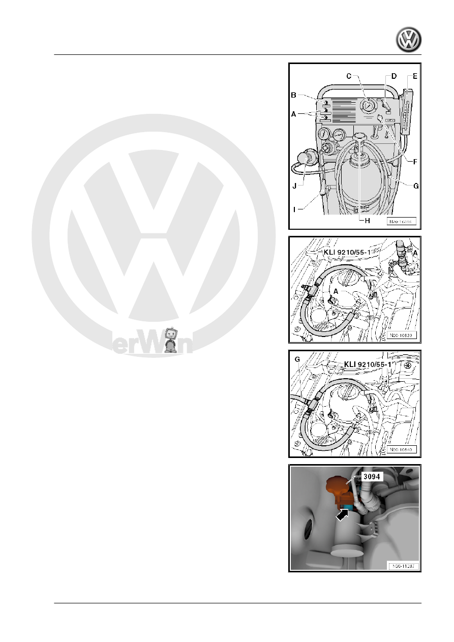
– Open the nitrogen bottle -H-.
– Connect the measuring hose -G- to the self-test connection

-B-.

– Set the valve -D- to “Test”.
– Using the pressure reducer -J- adjust the pressure to 25 mbar

(10 in. H2O).

– Set the valve -D- to “Hold”.
• The pressure must now be maintained for a minimum of two

minutes.
If the pressure is not maintained, check the tester.

Fuel System, Checking for Leaks:
– Connect the -KLI 9210/55-1- to the breather lines -A- “white

markings” as illustrated.

– Connect the measuring hose -G- from the -KLI 9210- to the -

KLI9210/55-1- .

– Connect the -KLI 9210- to the vehicle battery.
– Remove right rear wheel housing liner.

– Tightly close the hose to the air filter -arrow- using a hose

clamp.

– Set the valve -D- to “Test”. The fuel system is now filled.
– Watch the pressure gauge -C- and the flow meter -E-. The fuel

system is filled if the flow rate decreases and the pressure in‐

creases to 10 in. H2O (25 mbar).

– After the pressure has stabilized, set the valve -D- to “Hold”.
• The pressure must not drop below 8 in. H2O (20 mbar) after

five minutes.

If the pressure drops or if no pressure develops, then locate the

leak as follows:
– Set the valve -D- to “Test” and fill the system with smoke.
– While the fuel system is being filled, press the smoke gener‐

ator button -I- for approximately one minute.

The fuel system is now under pressure and filled with smoke.
– Check all the lines, hoses and the fuel filler cap for escaping

smoke.

Note

Illuminate components and hoses with a strong flood light, the

smoke will be more visible.

An ultrasonic sensor tester or commercially available leak

spray can also be used to locate leaks.

Depending on how long fault finding lasts, the smoke gener‐

ator button may need to be pressed again. This ensures there

is enough smoke present in the fuel system.

The installation opening inside the passenger compartment

must be opened to check the flange on the fuel pump and fuel

filter.

– Replace any leaking hoses or components.

7

Accelerator Mechanism

⇒ “7.1 Overview - Accelerator Pedal Module”, page 79
⇒ “7.2 Accelerator Pedal Position Sensors G79 / G185 , Remov‐

ing and Installing”, page 80

7.1

Overview - Accelerator Pedal Module

1 - Bolt

❑ 6 Nm

2 - Connector

❑ Pull on the connector to

make sure it is engaged

correctly and securely.

3 - Accelerator Pedal Module -

GX2-

❑ Contains

Accelerator Pedal Posi‐

tion Sensor - G79-

Accelerator Pedal Posi‐

tion Sensor 2 - G185-

❑ Removing and Instal‐

ling. Refer to

⇒ “7.2 Accelerator Ped‐

al Position Sensors

G79 / G185 , Removing

and Installing”,

page 80

 .

7.2

Accelerator Pedal Position Sensors -

G79- / -G185- , Removing and Installing

Removing
– Fold the carpet -1- forward in the direction of the -arrow-.

– Release and remove the connector -2- from the Accelerator

Pedal Module - GX2- .

– Remove the bolt -1-.
– Remove the accelerator pedal module -3- from the mounting.
Installing
Install in reverse order of removal. Note the following:
Tightening Specifications
♦ Refer to

⇒ “7.1 Overview - Accelerator Pedal Module”, page 79


Content   ..  751  752  753  754   ..