Volkswagen Golf / Golf GTI / Golf Variant. Manual - part 750


  Index      Volkswagen     Volkswagen Golf / Golf GTI / Golf Variant - service repair manual 2013 year


Search            copyright infringement  


Content   ..  748  749  750  751   ..


Volkswagen Golf / Golf GTI / Golf Variant. Manual - part 750


Version 6
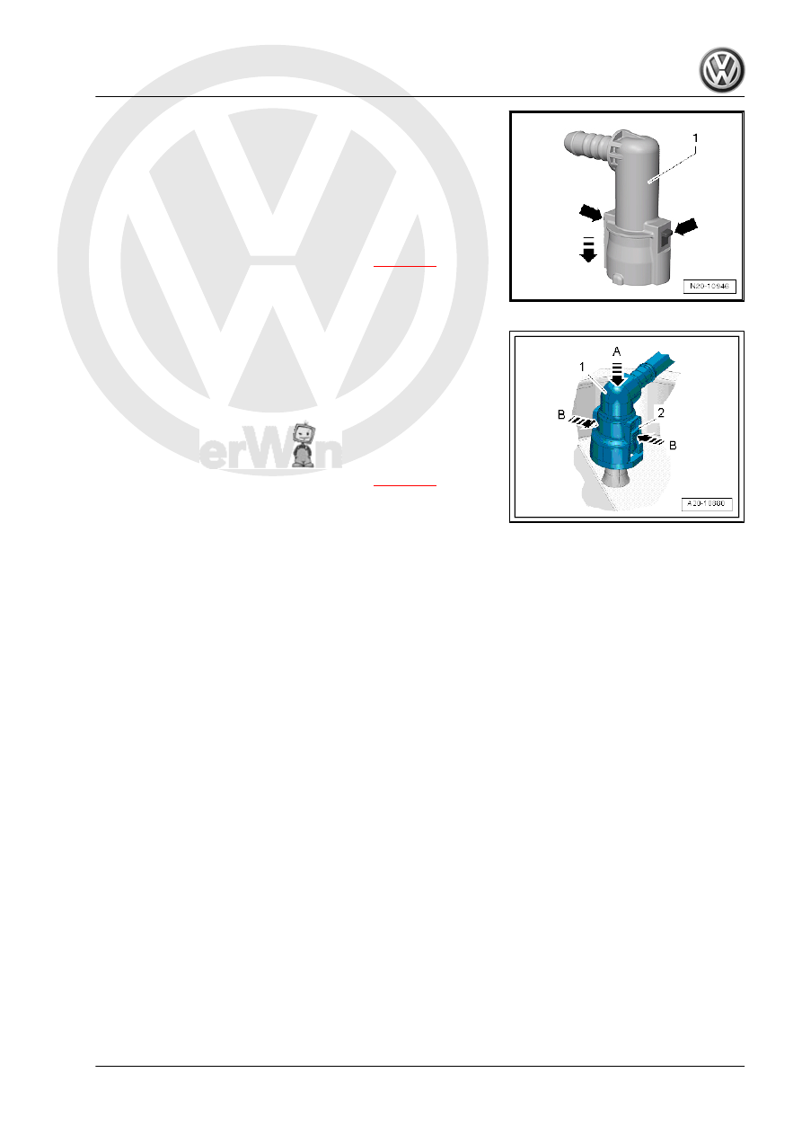
Connector coupling with right and left release buttons -arrows-:
Opening
– Press the connector coupling -1- in the direction of the

-arrow- and hold it down.

– Press the release buttons -arrows- and remove the connector

coupling.

Note the color coding when installing. Refer to 

⇒ page 62

 .

The connector couplings must »audibly« engage when locking.
– Pull on the connector coupling to check for secure fit.

Version 7
Connector coupling -1- with right and left release buttons -2-:
Opening
– Press the connector coupling -1- in direction of the -arrow A-

and hold it down.

– Push the release buttons -2- in the direction of -arrow B- and

remove the connector coupling -1-.

Note the color coding when installing. Refer to 

⇒ page 62

 .

The connector couplings must »audibly« engage when locking.
– Pull on the connector coupling to check for secure fit.

5

Fuel Filter

The pressure relief valve and the fuel filter are integrated in the

fuel delivery unit and cannot be replaced separately. Refer to

⇒ “2.1 Overview - Fuel Delivery Unit/Fuel Level Sensor”,

page 51

 .

6

EVAP System

⇒ “6.1 Connection Diagram - EVAP System”, page 67
⇒ “6.2 Overview - EVAP System”, page 69
⇒ “6.3 EVAP Canister, Removing and Installing”, page 70
⇒ “6.4 Fuel Tank, Checking Ventilation”, page 72
⇒ “6.5 Fuel System, Checking for Leaks”, page 76

6.1

Connection Diagram - EVAP System

⇒ “6.1.1 Connection Diagram - EVAP System, with Fuel Tank

Leak Detection”, page 67
⇒ “6.1.2 Connection Diagram - EVAP System, without Fuel Tank

Leak Detection”, page 68

6.1.1

Connection Diagram - EVAP System,

with Fuel Tank Leak Detection

Note

The fuel tank leak detection function is based on the premise that

the fuel systems creates a natural vacuum when the fuel in the

fuel tank becomes colder. The temperature and pressure meas‐

urements are required for the fuel tank leak detection. The tem‐

perature sensor is integrated in the Fuel Tank Leak Detection

Control Module - J909- . The Fuel Tank Pressure Sensor - G400-

is installed in the pressure regulating valve. The system is con‐

sidered to be closed when the measured vacuum is 2.5 mbar as

the fuel tank temperature drops. If there is no vacuum, then there

is a leak in the fuel system, which will result in an entry in the

engine control module Diagnostic Trouble Code (DTC) memory.

1 - EVAP Canister

❑ Component location:

under the wheel hous‐

ing liner in the right rear

wheel housing

❑ Removing and Instal‐

ling. Refer to

⇒ “6.3.2 EVAP Canister,

Removing and Instal‐

ling, without Fuel Tank

Leak Detection”,

page 71

 .

2 - Air Filter
3 - Pressure Regulating Valve

❑ With Fuel Tank Pres‐

sure Sensor - G400-

4 - Bleeder Line

❑ from EVAP canister to

engine

5 - Cap

❑ Seal must not be dirty or

damaged

6 - Fuel Tank Leak Detection

Control Module - J909-

❑ With temperature sen‐

sor

7 - Fuel Supply Line

❑ Black

8 - Bleeder Line

❑ White

9 - EVAP Canister Purge Reg‐

ulator Valve 1 - N80-

❑ Checking using the Vehicle Diagnostic Tester .

6.1.2

Connection Diagram - EVAP System,

without Fuel Tank Leak Detection

Connection Diagram on EVAP Canister
1 - -A- Vent Connection
2 - -T- Connection to Fuel Tank
3 - -M- to EVAP Canister Purge Regulator Valve 1 - N80-
4 - Cap


Content   ..  748  749  750  751   ..