Volkswagen Golf / Golf GTI / Golf Variant. Manual - part 749


  Index      Volkswagen     Volkswagen Golf / Golf GTI / Golf Variant - service repair manual 2013 year


Search            copyright infringement  


Content   ..  747  748  749  750   ..


Volkswagen Golf / Golf GTI / Golf Variant. Manual - part 749


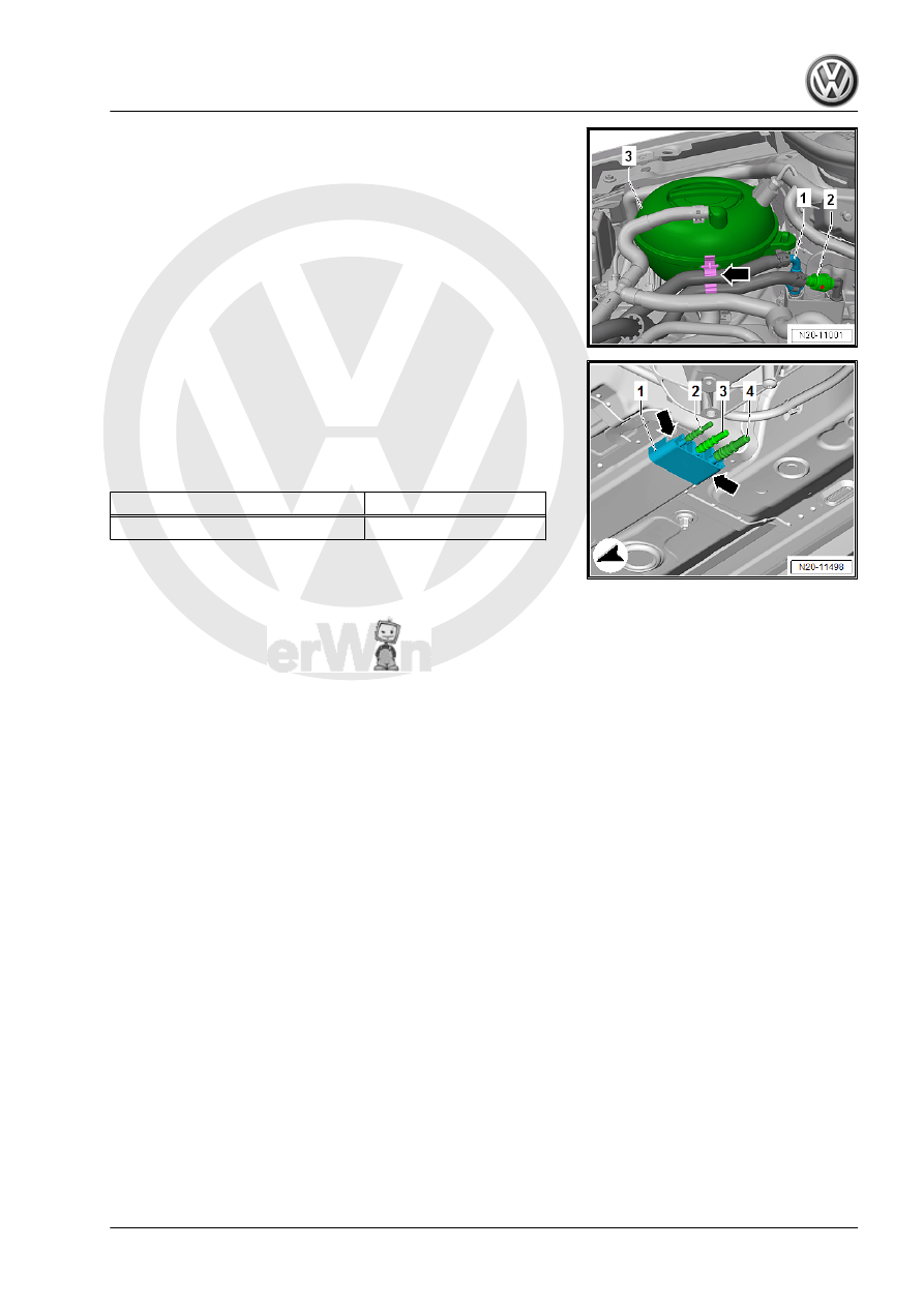
Installation Position of the Fuel Lines on the Coupling Point in

Engine Compartment:
1 - Fuel Supply Line
2 - Bleeder Line

Installation Position of the Fuel Lines on the Underbody:
2 - Parking/Auxiliary Heater Fuel Line
3 - Fuel Supply Line
4 - Bleeder Line
Tightening Specifications:

Component

Tightening Specification

Shield nut

8 Nm

♦ Refer to ⇒  Body Exterior; Rep. Gr.  66 ; Wheel Housing Liner;

Overview - Front Wheel Housing Liner .

♦ Refer to ⇒  Body Exterior; Rep. Gr.  66 ; Underbody Trim Panel;

Component Location Overview - Trim Panels .

4

Connector Couplings

⇒ “4.1 Connector Couplings, Disconnecting”, page 62

4.1

Connector Couplings, Disconnecting

Special tools and workshop equipment required
♦ Lever - Fuel Line - T10468-
Connector Coupling Allocation

Note

The connector couplings for fuel, vacuum and bleeder lines

are color-coded. There is either a colored dot on the connector

coupling, or the release button has the corresponding color.

Refer to 

⇒ page 62

 .

The connector couplings must »audibly« engage when lock‐

ing.

Pull on the connector coupling to check for secure fit.

Color Coding

Connector Coupling

Color Coding on Connector Coupling

Fuel supply

Black

Fuel Return Line

Blue

Bleeder

White beige

Vacuum

Green

WARNING

The fuel line is under pressure.
Fuel poses a risk of injury to the eyes and skin.
Wear protective eyewear and protective clothing to avoid injury

and contact with skin. Place a cleaning cloth around the con‐

nection  point  before  loosening  hose  connections.  Carefully

open the connection point to release the pressure.

Version 1
Connector coupling with right and left release buttons -arrows-.

Opening
It is necessary to counterhold the fuel separating point -1- inside

the engine compartment.
– Insert the -T10468- between the heat shield and the stop

-arrow- for the fuel line -2- and counterhold it.

Continue for all separation points on the fuel system:
– Push the connector coupling -1- in the direction of the

-arrow A-.

– Press the release buttons and hold it down.
– Disconnect the connector coupling -1- from the fuel line -2- in

the direction of the -arrow B-.

Note the color coding when installing. Refer to 

⇒ page 62

 .

The connector couplings must »audibly« engage when locking.
– Pull on the connector coupling to check for secure fit.

Version 2
Connector coupling with pull release -arrow-:

Opening
– Push the connector coupling -1- in the direction of the

-arrow A-.

– Pull the pull release -2- in the direction of the -arrow B-.
– Pull the connector coupling -1- off the fuel line -3- in the direc‐

tion of the -arrow B-.

Note the color coding when installing. Refer to 

⇒ page 62

 .

The connector couplings must »audibly« engage when locking.
– Pull on the connector coupling to check for secure fit.

Version 3
Connector coupling with front button -arrow-:
Opening
– Press the release button -arrow- and remove the connector

couplings.

Note the color coding when installing. Refer to 

⇒ page 62

 .

The connector couplings must »audibly« engage when locking.
– Pull on the connector coupling to check for secure fit.

Version 4
Connector coupling with right and left release button -arrows-:
Opening
– Push the connector coupling in the direction of the -arrow A-.
– Press the release buttons -arrows- and remove the connector

coupling.

Note the color coding when installing. Refer to 

⇒ page 62

 .

The connector couplings must »audibly« engage when locking.
– Pull on the connector coupling to check for secure fit.

Version 5
Connector coupling with right and left release buttons -arrows-:
Opening
– Press the release buttons -arrows- and remove the connector

coupling.

Note the color coding when installing. Refer to 

⇒ page 62

 .

The connector couplings must »audibly« engage when locking.
– Pull on the connector coupling to check for secure fit.


Content   ..  747  748  749  750   ..