Volkswagen Golf / Golf GTI / Golf Variant. Manual - part 747
 

  Index      Volkswagen     Volkswagen Golf / Golf GTI / Golf Variant - service repair manual 2013 year


Search            copyright infringement  


Content   ..  745  746  747  748   ..


Volkswagen Golf / Golf GTI / Golf Variant. Manual - part 747


– Drain the fuel tank. Refer to 

⇒ “1 Fuel Tank”, page 6

 .

Golf Sportsvan:
– Remove the right rear seat. Refer to ⇒  Body Interior; Rep. Gr. 

72 ; Rear Seats; Bench Seat / Single Seat, Removing and In‐

stalling .

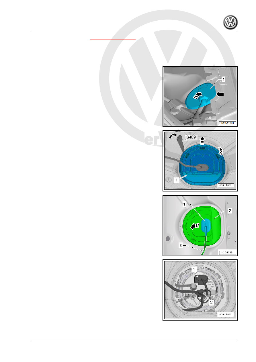
– Partially loosen the cover -1- in the carpet at the separating

line -arrow-.

– Do not separate the cover completely from the carpet so that

later it will be installed correctly.

– Only loosen so far that the cover can be folded up.
– Fold up the cover in the direction of the -arrow-.
Golf and Golf Wagon:
– Remove the rear bench seat. Refer to ⇒  Body Interior; Rep.

Gr.  72 ; Rear Seats; Bench Seat / Single Seats, Removing

and Installing .

Continuation for All Vehicles:
– Unclip the sealing flange cover -1- at the tabs -arrows- using

the Trim Removal Wedge - 3409- .

– Unclip the grommet -1- downward out of the cover -2-.
– Guide the cover -2- on the wiring harness -3- toward the rear.

– Unlock and disconnect the connector -1- from the sealing

flange.

– If equipped, disengage the connector -2- for the parking heater

Metering Pump - V54- on the sealing flange and move it to the

side.

– Remove the fuel line -1- from the sealing flange. Disconnect

the connector couplings. Refer to

⇒ “4.1 Connector Couplings, Disconnecting”, page 62

 .

WARNING

The fuel line is under pressure.
Fuel poses a risk of injury to the eyes and skin.
Wear protective eyewear and protective clothing to avoid injury

and contact with skin. Place a cleaning cloth around the con‐

nection  point  before  loosening  hose  connections.  Carefully

open the connection point to release the pressure.

– If equipped, remove the fuel line -2- to the Metering Pump -

V54- for the parking heater on the sealing flange.

– Loosen the lower hose clamp to do this.

– Open the locking ring using the Wrench - Fuel Sending Unit -

T10202- .

– Carefully lift the fuel delivery unit flange.

– Pull the sealing flange -2- out of the opening in the fuel tank

just a little.

– Remove the seal -1- at the fuel tank opening.
– Carefully pull the fuel delivery unit with the Fuel Gauge Sensor

- G- out through the opening in the fuel tank.

– Turn and tilt it as needed.
– Be careful not to bend the floater arm on the fuel level sensor

when removing the fuel delivery unit.

– Place a cloth underneath to catch the leaking fuel, since the

fuel delivery unit is still filled.

Vehicles with Suction Line in the Fuel Tank

– Pull the fuel delivery unit -2- as far as possible out of the fuel

tank.

– Release the fuel line -1- in the fuel tank and disconnect it from

the suction line -3-. Connector Couplings, Disconnecting. Re‐

fer to 

⇒ “4 Connector Couplings”, page 62

 .

Continuation for all Vehicles.

Note

If the delivery unit is being replaced, the old delivery unit must

be emptied before disposing of it.

Follow all waste disposal regulations.

Check the fuel tank for contamination.

Installing:
Install in reverse order of removal. Note the following:

Note

Disconnect the connector couplings. Refer to

⇒ “4.1 Connector Couplings, Disconnecting”, page 62

 .

Replace the gasket if damaged.

– Install the dry fuel delivery unit seal -1- into the opening in the

fuel tank.

– Be careful not to bend the fuel gauge sensor when installing

the fuel delivery unit.

– Coat the inside of the seal -1- with fuel.
– Push the sealing flange -2- down against the spring force.
– Bring the sealing flange into its installation position.

– The arrow -3- on the fuel tank must point to the mark -2- on

the sealing flange -1-.

– When inserting the sealing flange, the seal must not be dam‐

aged or crushed.

– Tighten the locking ring using the -T10202- .

– Attach the fuel line -1- to the sealing flange until it clicks into

place.

– If equipped, install the fuel line -2- to the Metering Pump - V54-

for the parking heater on the sealing flange. Refer to ⇒ 

Heating, Ventilation and Air Conditioning; Rep. Gr.  82 ; Fuel

Supply; Component Location Overview - Fuel Supply .

– Connect the connector -1-.
– If equipped, engage the connector -2- for the parking heater

Metering Pump - V54- on the sealing flange.

– Pull on the connector -1- to make sure it is secure.
– Fill the fuel tank with at least five liters of gasoline after instal‐

ling the fuel delivery unit.

Tightening Specifications
♦ Refer to

⇒ “2.1 Overview - Fuel Delivery Unit/Fuel Level Sensor”, page

51

2.3

Fuel Level Sensor - G- , Removing and

Installing

Removing
– Remove the fuel delivery unit. Refer to

⇒ “2.2 Fuel Delivery Unit/Fuel Level Sensor, Removing and

Installing”, page 52

 .

– Make a note of the colors of the cables -1- for installing later.


Content   ..  745  746  747  748   ..