Volkswagen Golf / Golf GTI / Golf Variant. Manual - part 746


  Index      Volkswagen     Volkswagen Golf / Golf GTI / Golf Variant - service repair manual 2013 year


Search            copyright infringement  


Content   ..  744  745  746  747   ..


Volkswagen Golf / Golf GTI / Golf Variant. Manual - part 746


Continuation for All Vehicles:
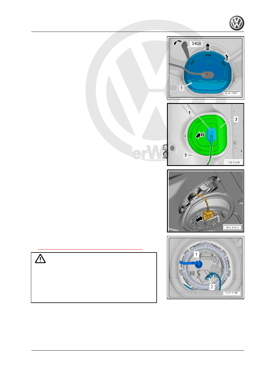
– Unclip the sealing flange cover -1- at the tabs -arrows- using

the Trim Removal Wedge - 3409- .

– Unclip the grommet -1- downward out of the cover -2-.
– Guide the cover -2- on the wiring harness -3- toward the rear.

– Release and disconnect the connector -arrow-.

– Remove the fuel line -1- from the sealing flange. Disconnect

the connector couplings. Refer to

⇒ “4.1 Connector Couplings, Disconnecting”, page 62

 .

WARNING

The fuel line is under pressure.
Fuel poses a risk of injury to the eyes and skin.
Wear protective eyewear and protective clothing to avoid injury

and contact with skin. Place a cleaning cloth around the con‐

nection  point  before  loosening  hose  connections.  Carefully

open the connection point to release the pressure.

– If equipped, remove the fuel line -2- to the Metering Pump -

V54- for the parking heater on the sealing flange.

– Loosen the lower hose clamp to do this.

– Open the locking ring using the Wrench - Fuel Sending Unit -

T10202- .

– Carefully lift the fuel delivery unit flange -3-.
– Remove the seal -1- and slightly lift the fuel delivery unit flange

again carefully.

– Attach the ground wire of the Fuel Extractor Unit to a bare area

on the body.

– Insert the suction hose for the Fuel Extraction Unit - VAS5190-

as deep as possible into the fuel tank.

– Extract the fuel using the Fuel Extractor Unit - VAS5190- .
If the fuel tank only needs to be drained, reinstall the fuel delivery

unit. Refer to

⇒ “2.2 Fuel Delivery Unit/Fuel Level Sensor, Removing and In‐

stalling”, page 52

 .

Tightening Specifications

⇒ “2.1 Overview - Fuel Delivery Unit/Fuel Level Sensor”, page

51

♦ Refer to ⇒  Heating, Ventilation and Air Conditioning; Rep. Gr. 

82 ; Fuel Supply; Component Location Overview - Fuel Sup‐

ply .

2

Fuel Delivery Unit/Fuel Level Sensor

⇒ “2.1 Overview - Fuel Delivery Unit/Fuel Level Sensor”,

page 51
⇒ “2.2 Fuel Delivery Unit/Fuel Level Sensor, Removing and In‐

stalling”, page 52
⇒ “2.3  Fuel Level Sensor G , Removing and Installing”,

page 56

2.1

Overview - Fuel Delivery Unit/Fuel Level Sensor

1 - Fuel Delivery Unit

❑ With the Transfer Fuel

Pump - G6-

❑ Cannot be replaced

separately with an inte‐

grated fuel filter

❑ Cannot be replaced

separately with an inte‐

grated pressure relief

valve

❑ Check the fuel pump

electronically using the

Vehicle Diagnostic

Tester ⇒ Vehicle diag‐

nostic tester.

❑ Removing and Instal‐

ling. Refer to

⇒ “2.2 Fuel Delivery

Unit/Fuel Level Sensor,

Removing and Instal‐

ling”, page 52

 .

❑ Fill the vehicle with at

least five liters of fuel af‐

ter installing

2 - Seal

❑ Replace
❑ Install dry

3 - Locking Ring

❑ 110 Nm
❑ Loosen and tighten us‐

ing the Wrench - Fuel

Sending Unit - T10202-

4 - Fuel Pump Control Module

- J538-

❑ Not on vehicles with en‐

gine code CWVA

❑ Check in 

Guided Fault Finding

 using the Vehicle Diagnostic Tester .

❑ Removing and Installing. Refer to

⇒ “8.2  Fuel Pump Control Module J538 , Removing and Installing”, page 116

 .

5 - Connector

❑ For Fuel Pump Control Module - J538-
❑ Make sure it is attached securely and pull on it to make sure the connector it is properly locked.

6 - Connector

❑ For the Transfer Fuel Pump - G6- and the Fuel Gauge Sensor - G-

❑ Make sure it is attached securely and pull on it to make sure the connector it is properly locked.

7 - Fuel Supply Line

❑ To the engine
❑ Do not kink
❑ To disconnect, press the release button on the connecting piece
❑ The connector couplings must »audibly« engage when locking.
❑ Pull on the connector coupling to check for secure fit.
❑ Connector Couplings, Disconnecting. Refer to 

⇒ “4.1 Connector Couplings, Disconnecting”, page 62

 .

8 - Fuel Gauge Sensor - G-

❑ Checking using the Vehicle Diagnostic Tester .
❑ Removing and Installing. Refer to 

⇒ “2.3  Fuel Level Sensor G , Removing and Installing”, page 56

 .

Fuel Delivery Unit Installation Position
• The arrow -3- on the fuel tank must point to the mark -2- on

the sealing flange -1-.

Fuel Lines to the Fuel Delivery Unit
1 - Fuel Supply Line
2 - Fuel line to Metering Pump - V54-

2.2

Fuel Delivery Unit/Fuel Level Sensor,

Removing and Installing

Special tools and workshop equipment required
♦ Wrench - Fuel Sending Unit - T10202-
♦ Torque Wrench 1332 40-200Nm - VAG1332-
♦ Trim Removal Wedge - 3409-
Removing

– Pay attention to all safety precautions. Refer to

⇒ “1 Safety Precautions”, page 1

 .

– Follow the guidelines for clean working conditions. Refer to

⇒ “3.1 Parking/Auxiliary Heater and Fuel System Clean Work‐

ing Conditions”, page 4

 .

– The fuel tank may be a maximum of 

3

/4 full. This ensures the

fuel level is below the fuel delivery unit flange.


Content   ..  744  745  746  747   ..