Volkswagen Golf / Golf GTI / Golf Variant. Manual - part 748


  Index      Volkswagen     Volkswagen Golf / Golf GTI / Golf Variant - service repair manual 2013 year


Search            copyright infringement  


Content   ..  746  747  748  749   ..


Volkswagen Golf / Golf GTI / Golf Variant. Manual - part 748


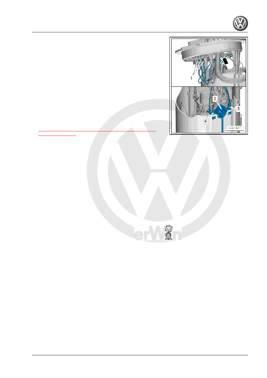
– Unlock and disconnect the connectors -1- from the sealing

flange.

– Disengage and free up the wires on the bracket -arrow-.
– Unlock the retainers -3- and -4-.
– Pull the Fuel Gauge Sensor - G- -2- upward.
– Bend back the hooks on the connector.
Installing:
– Install in reverse order of removal. Note the following.
– Pay attention to the color of the contacts.
– Pull on the connectors to make sure they are secure.
– Insert the Fuel Level Sensor - G- into the guide on the fuel

delivery unit and push downward until it engages.

– Install the fuel delivery unit. Refer to

⇒ “2.2 Fuel Delivery Unit/Fuel Level Sensor, Removing and

Installing”, page 52

 .

3

Wiring

⇒ “3.1 Fuel Lines, Removing and Installing”, page 58

3.1

Fuel Lines, Removing and Installing

Removing
– If equipped, remove the underbody trim panel in front of the

right rear axle. Refer to ⇒  Body Exterior; Rep. Gr.  66 ; Un‐

derbody Trim Panel; Component Location Overview - Trim

Panels .

– If necessary, remove the right underbody trim panel. Refer to

⇒  Body Exterior; Rep. Gr.  66 ; Underbody Trim Panel; Com‐

ponent Location Overview - Trim Panels .

– Disconnect the fuel lines on the underbody. Refer to

⇒ “4.1 Connector Couplings, Disconnecting”, page 62

 .

– Unclip the bracket -1- from the underbody -arrows-.
– Unclip the bracket -1- from the fuel lines.
– Secure using a pulling aid (for example a cable or string) on

the fuel lines.

– This pulling aid make the reinstallation easier, to do so select

enough length.

– Use adhesive tape to secure the pulling aid.

– Remove fuel supply line -1 and 2-. Disconnect the connector

couplings. Refer to

⇒ “4.1 Connector Couplings, Disconnecting”, page 62

 .

WARNING

The fuel line is under pressure.
Fuel poses a risk of injury to the eyes and skin.
Wear protective eyewear and protective clothing to avoid injury

and contact with skin. Place a cleaning cloth around the con‐

nection  point  before  loosening  hose  connections.  Carefully

open the connection point to release the pressure.

– Unclip the fuel lines -1 and 2- from the bracket -arrow- on the

coolant expansion tank -3-.

– Disconnect the connector -1-.
– Open the bracket and remove the coolant hoses from the en‐

gine.

– Release the retainers with a screwdriver -arrow- and move the

coolant expansion tank to the side.

– Open the bracket for the refrigerant lines on the right wheel

housing.

– Unclip the refrigerant lines.

– If equipped remove the heat shield -1- from the ABS Hydraulic

Unit - N55- .

– To do so, unclip the heat shield -1- from the bracket -2-

-arrow-.

Vehicles with Parking Heater:
– Remove the front section of the wheel housing liner or right

front wheel housing liner. Refer to ⇒  Body Exterior; Rep. Gr. 

66 ; Wheel Housing Liner; Overview - Front Wheel Housing

Liner .

– Unlock and remove the fuel line -7-.
– Catch escaping fuel using cleaning cloths.
– Unclip the fuel line from the bracket and guide out.
– Remove the bracket for the refrigerant lines from the body.
– Guide the fuel line under the refrigerant lines and the engine

mount.

Continuation for All Vehicles:
– Unclip the shield -1- on the stud bolt from the body -arrow A-.
– Unclip the shield -1- from the longitudinal member -2-.
– If equipped, loosen the clip -4- for the parking/auxiliary heater

fuel line -3- from the body.

– Unclip the bracket -2- for the shield from the longitudinal mem‐

ber.

– Remove the lines upward.
– At the same time turn the lines, but do not tear!
Installing:
Install in reverse order of removal. Note the following:

Note

The fuel line, bleed pipe, and fuel line for the parking/auxiliary

heater are installed together.

Secure the lines for example with adhesive tape.

– Remove the pulling aid from the old lines.
– Insert the lines as shown in the shield guide and clip in. Refer

to 

⇒ page 60

 .

– The fuel lines are clipped in the at the top after guiding in.
– Pay attention that the plug is seated correctly on the new lines.
– Seal the lines with suitable plugs from the Engine Bung Set -

VAS6122- .

– Secure the pulling aid on the fuel lines.
– Use adhesive tape to secure the pulling aid.
– Pay attention that the pulling aid is only secured in the front

area of the lines.

– At the bottom seal the shield from the slotted guide with ad‐

hesive tape so that the lines do not slide out.

– Place the fuel lines together with the shield on the opening in

the longitudinal member.

Installation Position of Fuel Lines on the Shield:
1 - Fuel Supply Line
2 - Parking/Auxiliary Heater Fuel Line
3 - Guide for the Parking/Auxiliary Heater Fuel Line
4 - Lower line guide
5 - Bracket for the Lines in the Coupling Rod Area
6 - Bleeder Line


Content   ..  746  747  748  749   ..