Volkswagen Golf / Golf GTI / Golf Variant. Manual - part 688


  Index      Volkswagen     Volkswagen Golf / Golf GTI / Golf Variant - service repair manual 2013 year


Search            copyright infringement  


Content   ..  686  687  688  689   ..


Volkswagen Golf / Golf GTI / Golf Variant. Manual - part 688


Note

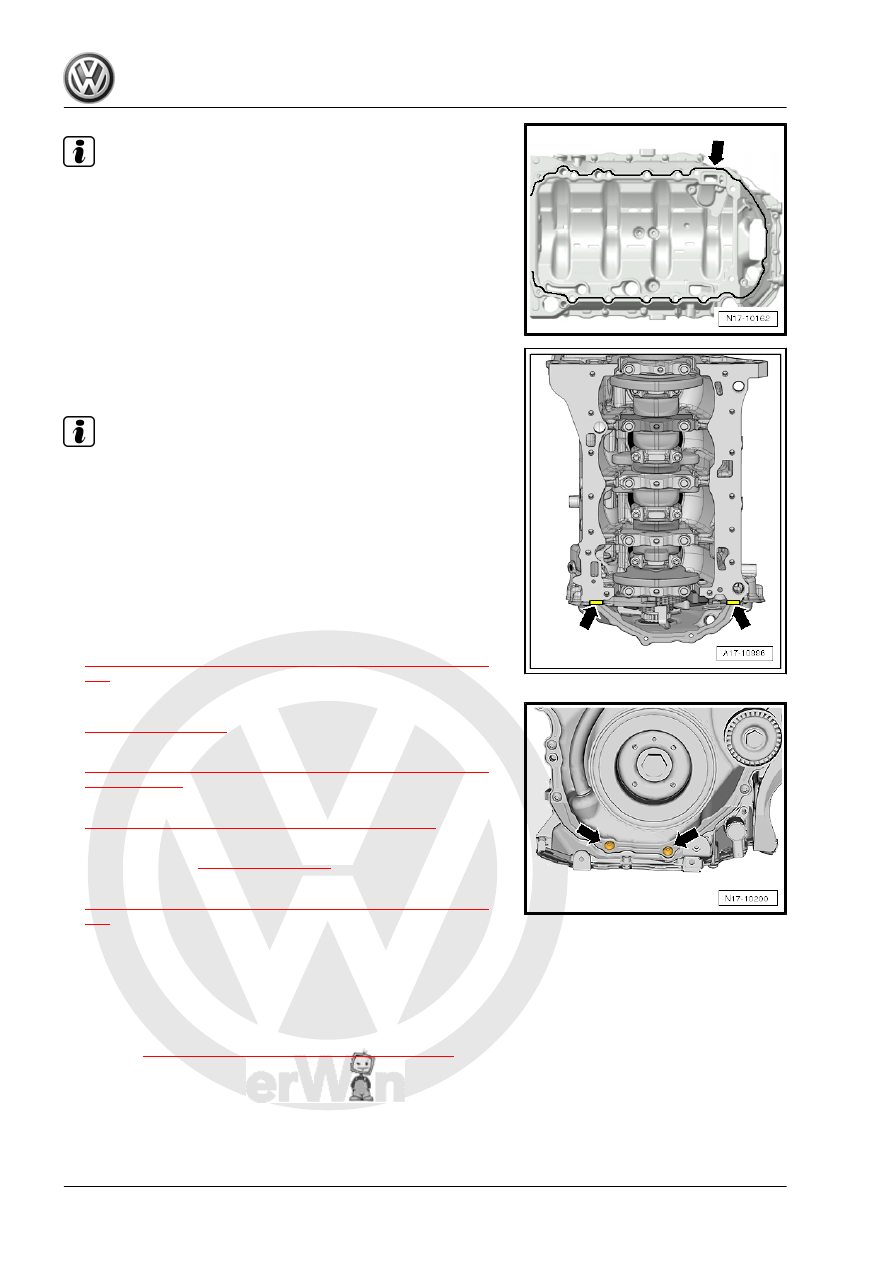
The lubrication system could be plugged with excess sealant. Do

not apply sealant bead thicker than indicated.

– Apply the silicone sealant on the clean sealing surface of the

upper oil pan section as shown -arrows-.

• Sealant bead thickness: 2 to 3 mm.

– Apply the silicon sealant, as shown in the illustration

-arrows-, between the cylinder block and the timing chain

guard lower section.

Note

The oil pan upper section must be installed within 5 minutes

after application of silicone sealant.

The sealant bead may not be thicker than specified, otherwise

excess sealant could enter the oil pan and clog the oil intake

tube.

• On the transmission side, the upper part of the oil pan and the

crankcase must align.

– Position the upper section of the oil pan immediately and tight‐

en the bolts, tightening sequence. Refer to Tightening se‐

quence. Refer to

⇒ Fig. ““Oil Pan Upper Section - Tightening Sequence”“ , page

181

 .

– Install the bolts -arrows-. Tightening specifications -item 16-

⇒ Item 16 (page 105)

 .

– Install the rear sealing flange. Refer to

⇒ “2.3 Sealing Flange, Removing and Installing, Transmission

Side”, page 59

 .

– Install the oil pump. Refer to

⇒ “1.5 Oil Pump, Removing and Installing”, page 188

 .

– Insert the new oil baffle and attach it. Tightening specification.

Refer to -item 7- 

⇒ Item 7 (page 180)

 .

– Install oil pan lower section. Refer to

⇒ “1.3 Oil Pan Lower Section, Removing and Installing”, page

182

 .

Assemble in reverse order of disassembly.
– Fill with engine oil and then check the level. Refer to ⇒ Main‐

tenance ; Booklet  36.1 ; Procedure Descriptions; Engine Oil,

Draining, Replacing Oil Filter, and Filling .

Tightening Specifications
♦ Refer to 

⇒ “1.1 Overview - Oil Pan/Oil Pump”, page 179

 .

1.5

Oil Pump, Removing and Installing

Special tools and workshop equipment required
♦ Elbow Assembly Tool - T10118-

♦ Chain Tensioner Locking Tool - T40265-

Caution

This procedure contains mandatory replaceable parts. Refer

to component overview prior to starting procedure.

Mandatory Replacement Parts
♦ Bolts - Oil Baffle
♦ Bolts - Oil Pump
♦ Oil Baffle

Note

There are plastic ribs on the oil baffle that deform permanently

when tightening. The plastic ribs ensure the oil baffle has no play

and does not rattle. Because of this, always replace the oil baffle

after removal.

Removing
– Remove the oil pan lower section. Refer to

⇒ “1.3 Oil Pan Lower Section, Removing and Installing”, page

182

 .

– Remove bolt -arrow- and oil baffle.

– Pull the chain tensioner spring using the Elbow Assembly Tool

- T10118- in direction of -arrow- and secure it with the Chain

Tensioner Locking Tool - T40265- .

– Remove the bolts -arrows- and the oil pump.
Installing
Install in reverse order of removal and note the following:
– Make sure there are both alignment bushings for centering the

oil pump.

– Check the oil intake pipe screen and the oil channels in the oil

pan upper section for contamination before installing the oil

pump.

– Guide the oil pump chain sprocket into the drive chain and

install the oil pump.

– Pull the chain tensioner spring with the Elbow Assembly Tool

- T10118- in the direction of -arrow- and remove the Chain

Tensioner Locking Tool - T40265- .

– Slowly release the Elbow Assembly Tool - T10118- .
– Place the O-ring -item 9- 

⇒ Item 9 (page 180)

 on the new oil

baffle and coat with engine oil.

– Insert the new oil baffle and secure it. Tightening specification.

Refer to -item 7- 

⇒ Item 7 (page 180)

 .

– Install the oil pan lower section. Refer to

⇒ “1.3 Oil Pan Lower Section, Removing and Installing”, page

182

 .

– Fill with engine oil and then check the level. Refer to ⇒ Main‐

tenance ; Booklet  ; Engine; Draining; Oil Filter, Replacing;

Engine Oil, Filling .

Tightening Specifications
♦ Refer to 

⇒ “1.1 Overview - Oil Pan/Oil Pump”, page 179

1.6

Oil Level Thermal Sensor - G266- , Re‐

moving and Installing

Caution

This procedure contains mandatory replaceable parts. Refer

to component overview prior to starting procedure.

Mandatory Replacement Parts
♦ O-ring - Oil Level Thermal Sensor
Removing
– Drain the engine oil. Refer to ⇒ Maintenance ; Booklet  36.1 ;

Procedure Descriptions; Engine Oil, Draining, Replacing Oil

Filter, and Filling .

– Remove the noise insulation. Refer to ⇒  Body Exterior; Rep.

Gr.  66 ; Noise Insulation; Overview - Noise Insulation .

– Disconnect the connector -3-.
– Remove the nuts -1- and the Oil Level Thermal Sensor - G266-

-4-.

Installing
Install in reverse order of removal. Note the following:
– Replace the O-ring -2-.
– Fill with engine oil and then check the level. Refer to ⇒ Main‐

tenance ; Booklet  36.1 ; Procedure Descriptions; Engine Oil,

Draining, Replacing Oil Filter, and Filling .

Tightening Specifications
♦ Refer to 

⇒ “1.1 Overview - Oil Pan/Oil Pump”, page 179


Content   ..  686  687  688  689   ..