Volkswagen Golf / Golf GTI / Golf Variant. Manual - part 689
2
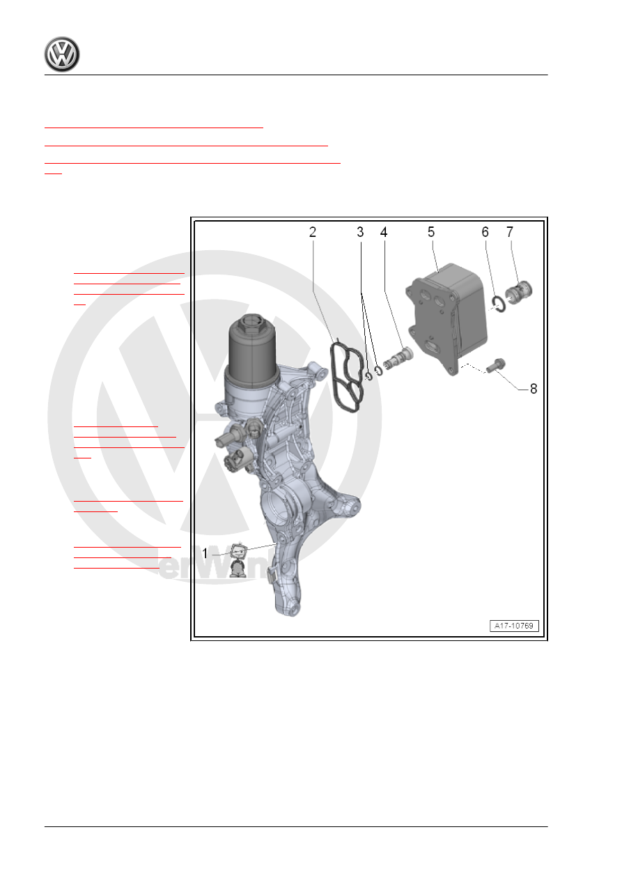
Engine Oil Cooler
⇒ “2.1 Overview - Engine Oil Cooler”, page 192
⇒ “2.2 Engine Oil Cooler, Removing and Installing”, page 192
⇒ “2.3 Mechanical Switch Valve, Removing and Installing”, page
2.1
Overview - Engine Oil Cooler
1 - Auxiliary Components
Bracket
❑ Removing and instal‐
ling. Refer to
2 - Seal
❑ Replace after removing
3 - O-Rings
❑ Replace after removing
❑ Coat with engine oil
4 - Mechanical Switch Valve
❑ Replacing. Refer to
.
5 - Engine Oil Cooler
❑ See note. Refer to
❑ Removing and instal‐
ling. Refer to
6 - Seal
❑ Replace after removing
❑ Coat with coolant
7 - Connection
8 - Bolt
❑ 8 Nm + 45° turn
❑ Replace after removing
2.2
Engine Oil Cooler, Removing and Instal‐
ling
Special tools and workshop equipment required
♦ Shop Crane - Drip Tray - VAS6208-