Volkswagen Golf / Golf GTI / Golf Variant. Manual - part 687


  Index      Volkswagen     Volkswagen Golf / Golf GTI / Golf Variant - service repair manual 2013 year


Search            copyright infringement  


Content   ..  685  686  687  688   ..


Volkswagen Golf / Golf GTI / Golf Variant. Manual - part 687


♦ Hand Drill with Plastic Brush Attachment
♦ Protective Eyewear
♦ Silicone sealant. Refer to Parts Catalog.

Caution

This procedure contains mandatory replaceable parts. Refer

to component overview prior to starting procedure.

Mandatory Replacement Parts
♦ Bolts - Oil Pan
♦ Bolt - Oil Baffle
♦ Gasket - Drain Plug
♦ Oil Baffle

Note

There are plastic ribs on the oil baffle that deform permanently

when tightening the oil pan lower section. The plastic ribs ensure

the oil baffle has no play and does not rattle. Because of this,

always replace the oil baffle.
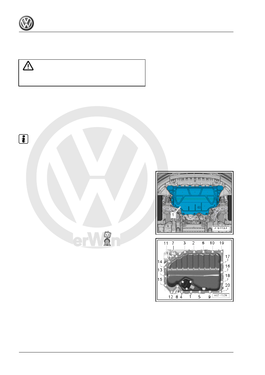
Removing
– Remove the noise insulation -1-. Refer to ⇒  Body Exterior;

Rep. Gr.  66 ; Noise Insulation; Overview - Noise Insulation .

– Place the Used Oil Collection and Extraction Unit -

SMN372500- under the engine and drain the engine oil.

– Remove the bolts -1 through 20- and remove the oil pan.

– Remove the bolt -1- and remove the oil baffle -2-.

Installing
– Install a new oil baffle. Tightening specification. Refer to

-item 7- 

⇒ Item 7 (page 180)

 .

– Remove the sealant residue and clean the sealing surface.
– Apply silicone sealant on the sealing surface of the oil pan

lower section as shown.

– Tighten the new bolts -1 through 20- in two stages in the se‐

quence shown:

Step

Tightening Sequence and

Tightening Specification

1. Bolts -1- through -20-

Pre-tighten to 8 Nm

2. Bolts -1- through -20-

45° additional turn

– Fill with engine oil and then check the level. Refer to ⇒ Main‐

tenance ; Booklet  ; Engine; Draining; Oil Filter, Replacing;

Engine Oil, Filling .

1.4

Oil Pan Upper Section, Removing and

Installing

Special tools and workshop equipment required
♦ Elbow Assembly Tool - T10118-
♦ Chain Tensioner Locking Tool - T40265-
♦ Hand drill with plastic brush attachment
♦ Protective eyewear
♦ Silicone grease. Refer to the Parts Catalog.

Caution

This procedure contains mandatory replaceable parts. Refer

to component overview prior to starting procedure.

Mandatory Replacement Parts
♦ Bolts - Upper Oil Pan

♦ Bolts - Lower Timing Chain Cover
Removing
• The transmission is removed.
– Remove the oil pan lower section. Refer to

⇒ “1.3 Oil Pan Lower Section, Removing and Installing”, page

182

 .

– Remove the rear sealing flange. Refer to

⇒ “2.3 Sealing Flange, Removing and Installing, Transmission

Side”, page 59

 .

– Remove the oil pump. Refer to

⇒ “1.5 Oil Pump, Removing and Installing”, page 188

 .

– Disconnect the connector -1-.

– Remove the bolts -arrows-.

– Remove the bolts -1 through 14-.
– First pry the upper section oil pan out on the transmission side.

When prying out, be careful not to bend the timing chain cover.

Installing

Note

Be sure to check the expiration date of the silicone sealant.

The oil pan (upper part) must be installed within five minutes

after application of silicone sealant.

Replace the bolts that were tightened with an additional turn.

Replace the gaskets, seals and self-locking nuts.

– Remove any sealant residue on the cylinder block using a flat

blade scraper.

CAUTION

Risk of injuring the eyes from sealant residue.
– Wear protective eyewear.

– Remove any remaining sealant on oil pan upper section using,

for example, a rotating plastic brush.

Note

See if the timing chain cover is deformed. Then mount the upper

section of the oil pan without any sealant and check the gap be‐

tween the cover and the top section. If deformation is found and

the cover can no longer be aligned, the cover must be replaced

after installing the oil pan upper section.

– Clean the sealing surfaces. They must be free of oil and

grease.

– Check for dirt in the oil passages in the oil pan upper section

and in the crankshaft housing.

– Cut the tube nozzle at the front marking (nozzle diameter: ap‐

proximately 2 mm).


Content   ..  685  686  687  688   ..