Volkswagen Golf / Golf GTI / Golf Variant. Manual - part 686
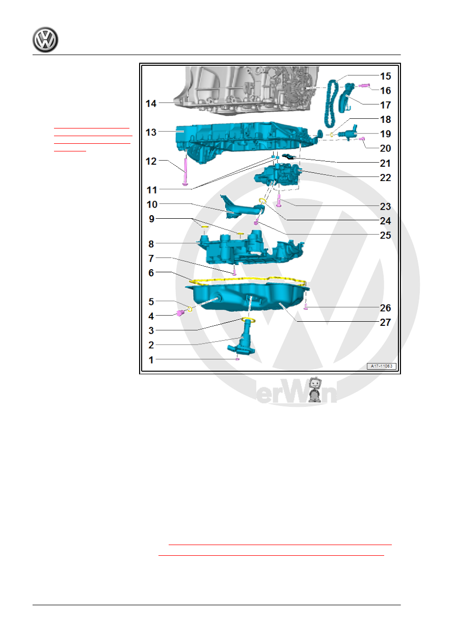
1 - Nut
❑ 9 Nm
2 - Oil Level Thermal Sensor -
G266-
❑ Removing and instal‐
ling. Refer to
3 - 0-Ring
❑ Replace after removing
❑ Coat with engine oil
4 - Oil Drain Plug/Plug
❑ Sheet metal oil pan: 30
Nm
❑ Plastic oil pan: turn us‐
ing the Oil Drain Plug
Assembly Tool -
T10549- until it stops
5 - Gasket/O-Ring
❑ Replace the gasket after
removal
❑ Replace the O-ring if
there are leaks
6 - Seal/Liquid Sealant
❑ Refer to parts catalog
7 - Bolt
❑ 4 Nm + 45°
❑ Replace after removing
❑ For the oil baffle and oil
intake pipe
8 - Oil Baffle
❑ There are plastic ribs on the oil baffle that deform permanently when tightening the oil pan lower section.
The plastic ribs ensure the oil baffle has no play and does not rattle. Because of this, always replace the
oil baffle.
9 - O-Ring
❑ Replace after removing
❑ Coat with engine oil
10 - Oil Intake Pipe
❑ Clean the screen if there are debris
11 - Centering Bracket
12 - Bolt
❑ Replace after removing
❑ Coat with engine oil
13 - Oil Pan Upper Section
❑ Removing and installing. Refer to
⇒ “1.4 Oil Pan Upper Section, Removing and Installing”, page 185
.
❑ Tightening sequence. Refer to
⇒ Fig. ““Oil Pan Upper Section - Tightening Sequence”“ , page 181
.
14 - Cylinder Block
15 - Oil Pump Drive Chain
❑ Mark direction of rotation before removing