Volkswagen Golf / Golf GTI / Golf Variant. Manual - part 665


  Index      Volkswagen     Volkswagen Golf / Golf GTI / Golf Variant - service repair manual 2013 year


Search            copyright infringement  


Content   ..  663  664  665  666   ..


Volkswagen Golf / Golf GTI / Golf Variant. Manual - part 665


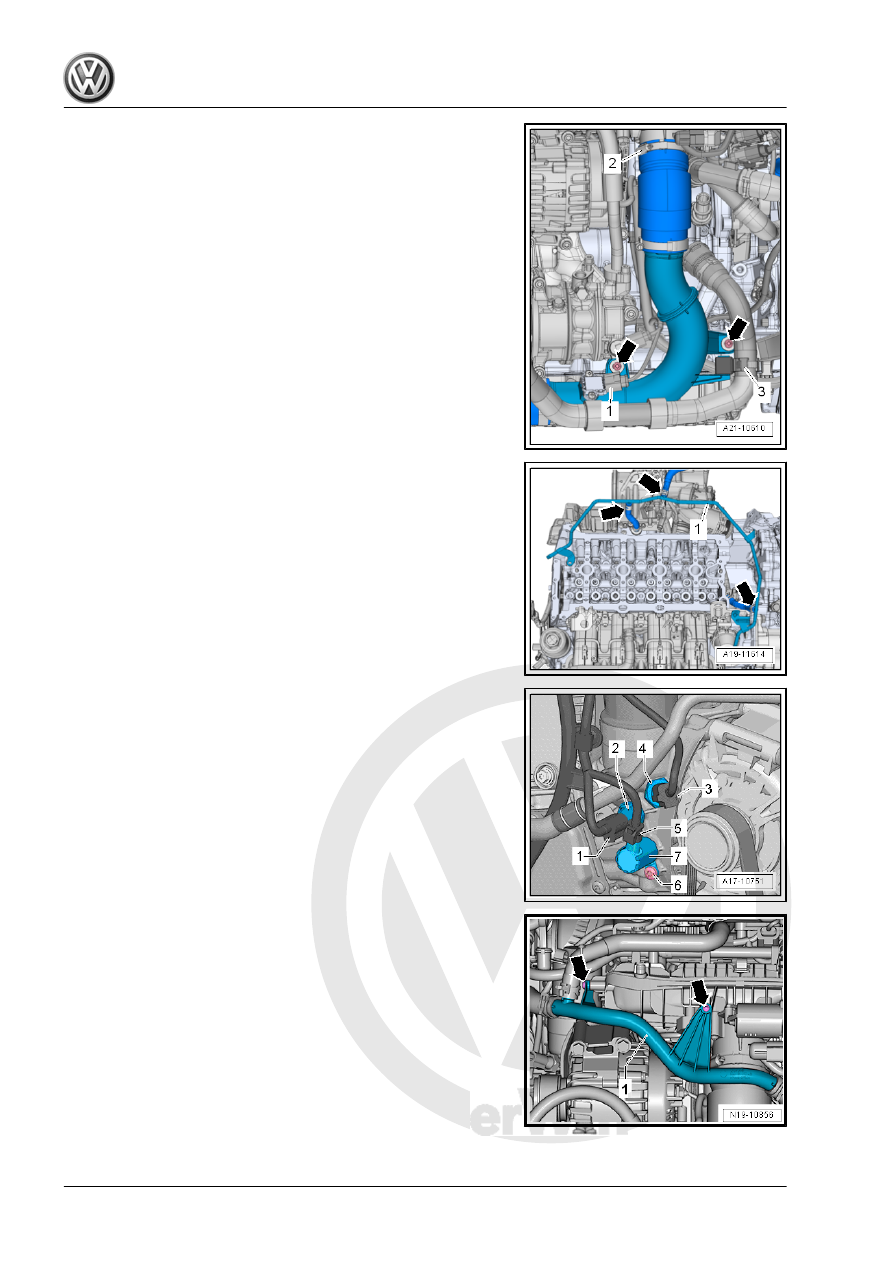
– Loosen the hose clamp -2-.
– Free up the coolant hose -3-.
– Remove the bolts -arrows-.
– Disconnect the connector -1- from the Charge Air Pressure

Sensor - G31- , and remove the right air guide pipe.

– Loosen the clamps -arrows- and remove the coolant hoses.
– Swing the coolant line -1- to the side.

– Disconnect the connectors:
1 - For Oil Pressure Switch - F22-
2 - For Reduced Oil Pressure Switch - F378-
5 - For Piston Cooling Nozzle Control Valve - N522-

– Remove the bolts -arrows-.

– Remove the bolt -1- and the nut -3- and then remove the

bracket -2- for the intake manifold.

– Disconnect the connectors:
1 - For Throttle Valve Control Module - GX3-
2 - For Intake Manifold Sensor - GX9-
3 - For Fuel Pressure Sensor - G247-
– Remove the connector -4- from the bracket.
– Free up the wiring harness and push it to the side.

– Free up the wiring harness -1 and 2- from the air guide pipe.
– Loosen the screw-type clamp -3-.
– Remove the bolts -arrows-.

– Loosen the hose clamp -arrow- and remove the charge air

hose -1- with the air guide pipe downward.

– Disconnect the connector -3- for Knock Sensor 1 - G61- from

the bracket.

– Disconnect the connectors -2 through 4-.

– Disconnect the connectors and free up the wires.
1 - For Intake Manifold Runner Control Valve - N316-
2 - For Coolant Shut-Off Valve - N82-
3 - For Engine Coolant Temperature Sensor - G62-
4 - For Oil Pressure Switch, Level 3 - F447-
– Remove the bolts -arrows-.

– Remove the bolts -arrows- and nut -1-.
– Remove the heat shield -2-.

– Remove the bolt -1-. Just loosen bolt -3-.
– Remove the turbocharger bracket -2-.

– Remove the nuts -arrows-.
– Remove the turbocharger from the cylinder head and tie up

behind.

– Remove the bolts -arrows-.
– Remove the cylinder head bolts in the sequence -1 to 10-.

Note

Make sure all wires and cables are disconnected.

– Remove the cylinder head and place it on a soft surface

(foam).

Installing

Note

Replace the bolts that were tightened with an additional turn.

Replace the gaskets, seals and self-locking nuts.

The hose supports, air guide pipes and hoses must be free of

oil and grease before installing.

Secure hose connections with standard production clamps.

Refer to the Parts Catalog.

The screws on the used clamps must be sprayed with a rust

remover before installing.

– Only unpack new cylinder head gasket immediately prior to

installation. The silicon layer and the cylinder head seal re‐

cessed area must not be damaged.

– Carefully remove sealant residue from cylinder head and cyl‐

inder block. Make sure that no long scrapes or scratches

result. Carefully remove all grinding and sanding residue.

– Clean the cylinder head bolt blind holes. If necessary with

compressed air.

– Set cylinder head gasket in place.


Content   ..  663  664  665  666   ..