Volkswagen Golf / Golf GTI / Golf Variant. Manual - part 666


  Index      Volkswagen     Volkswagen Golf / Golf GTI / Golf Variant - service repair manual 2013 year


Search            copyright infringement  


Content   ..  664  665  666  667   ..


Volkswagen Golf / Golf GTI / Golf Variant. Manual - part 666


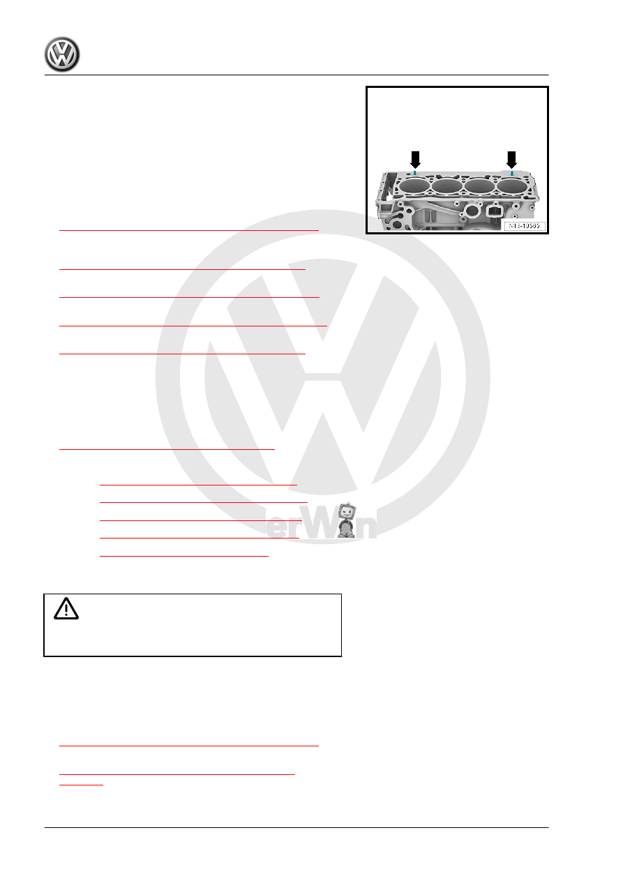
♦ Pay attention to centering pins in cylinder block -arrows-.
♦ Cylinder head gasket installed position: the part number must

be readable from the intake side.

– If the crankshaft was turned in the meanwhile: bring the piston

for cylinder 1 to Top Dead Center (TDC) and then turn the

crankshaft back just a little. Take care not to damage the timing

chain in the process.

– Set cylinder head in place.
– Install and tighten the cylinder head bolt. Tightening se‐

quence. Refer to

⇒ Fig. ““Cylinder Head Tightening Sequence”“ , page 92

– Install the camshaft but the camshaft timing chain is not in‐

stalled yet. Refer to

⇒ “4.2 Camshaft, Removing and Installing”, page 136

 .

– Support the engine in its installed position again. Refer to

⇒ “2.5 Engine, Supporting in Installed Position”, page 33

 .

– Remove the engine mount and the engine support. Refer to

⇒ “1.6 Engine Support, Removing and Installing”, page 55

 .

– Now install the camshaft timing chain. Refer to

⇒ “4.2 Camshaft, Removing and Installing”, page 136

 .

Further assembly is performed in the reverse order of removal,

thereby observing the following:
– Replace the engine oil. Refer to ⇒ Maintenance ; Booklet 

36.1 ; Procedure Descriptions; Engine Oil, Draining, Replacing

Oil Filter, and Filling .

– Fill with new coolant. Refer to

⇒ “1.3 Coolant, Draining and Filling”, page 217

 .

Tightening Specifications
♦ Refer to 

⇒ “1.1 Overview - Cylinder Head”, page 90

 .

♦ Refer to 

⇒ “4.1 Overview - Intake Manifold”, page 296

 .

♦ Refer to 

⇒ “3.1 Overview - Coolant Pipes”, page 241

 .

♦ Refer to 

⇒ “1.1 Overview - Turbocharger”, page 256

 .

♦ Refer to 

⇒ “1.1 Overview - Muffler”, page 338

 .

1.4

Vacuum Pump, Removing and Installing

Caution

This procedure contains mandatory replaceable parts. Refer

to component overview prior to starting procedure.

Mandatory Replacement Parts
♦ Seal - Vacuum Pump
Removing
– Remove the engine cover. Refer to

⇒ “3.1 Engine Cover, Removing and Installing”, page 38

 .

– Remove the air filter housing. Refer to

⇒ “3.2 Air Filter Housing, Removing and Installing”,

page 294

 .

– Unclip the vacuum line -2- from the bracket -arrow-.
– Disconnect the vacuum hose -2-.

– Remove the bolts -1, 2 and 3- and carefully move the coolant

line slightly to the side.

NOTICE

Risk of destroying the coolant pipes through deformation.
– Never change the coolant pipe bent shape.

– Remove the high pressure pump with the roller tappet. Refer

to

⇒ “7.2 High Pressure Pump, Removing and Installing”,

page 328

 .

– Remove the bolts -arrows- and remove the vacuum pump.

Note

Do not disassemble the vacuum pump.

Installing
– Clean the sealing surfaces.
– Turn the vacuum pump coupling plate so that it engages in the

camshaft groove when installing the vacuum pump.

– Position the new seal on the vacuum pump and insert the two

bolts. Position the vacuum pump with the seal on the cylinder

head.

– While doing so pay attention that it lays flush on the flange.
Further assembly is performed the reverse order of the removal.
Tightening Specifications
♦ Refer to

⇒ Fig. ““Vacuum Pump - Tightening Specifications”“ ,

page 94

1.5

Compression Pressure, Checking

Special tools and workshop equipment required
♦ Spark Plug Removal Tool - 3122B-

♦ Compression Tester Kit - VAG1763-
♦ Compression Tester Kit - Adapter 1 - VAG1381/1-
♦ Compression Tester Kit - Adapter 5A - VAG1381/5A-
Test Sequence

Note

Engine oil temperature: minimum 30 °C (86 °F)

Battery voltage at least 12.7 V

– Remove the engine cover. Refer to

⇒ “3.1 Engine Cover, Removing and Installing”, page 38

 .

– Disconnect the ignition coil sensors connectors and remove

them from the ignition coils at the same time.

– Remove the ignition coil bolts and remove the ignition coils.
– Disconnect the connectors:
1 - For Fuel Injector -N30- to -N33-
2 - For Cylinder 1 Fuel Injector 2 - N532- to Cylinder 4 Fuel

Injector 2 - N535-

– Remove spark plugs with Spark Plug Removal Tool - 3122B- .

– Check the compression pressure using the Compression

Tester Kit - VAG1763- , Compression Tester Kit - Adapter 1 -

VAG1381/1- and Compression Tester Kit - Adapter 5A -

VAG1381/5A- .

Note

For information on using the tester. Refer to the Operating In‐

structions.

– Operate the starter until the tester no longer indicates that the

pressure is increasing.

Compression Pressure

Pressure

New

11.0 to 14.0 bar

(159.54 to

203.05 psi)

Wear limit

7.0 bar (101.52

psi)

Maximum difference between cylinders

3.0 bar (43.5 psi)

– Install the spark plugs. Refer to ⇒ Maintenance ; Booklet  36.1 ;

Procedure Descriptions; Spark Plugs, Replacing .

– Install the ignition coils. Refer to

⇒ “1.3 Ignition Coils with Power Output Stages, Removing and

Installing”, page 357

 .

Note

By separating the connections, Diagnostic Trouble Code (DTCs)

are stored to memory. After the test, check and erase the DTC

memory.

– Turn on the ignition and select the following menu items on the

Vehicle Diagnostic Tester :

01 - Engine Electronics

Guided Functions

01 - Generate Readiness Code


Content   ..  664  665  666  667   ..