Volkswagen Golf / Golf GTI / Golf Variant. Manual - part 664
 

  Index      Volkswagen     Volkswagen Golf / Golf GTI / Golf Variant - service repair manual 2013 year


Search            copyright infringement  


Content   ..  662  663  664  665   ..


Volkswagen Golf / Golf GTI / Golf Variant. Manual - part 664


14 - O-Ring

❑ Coat with coolant
❑ Replace after removing

15 - Connection

❑ For coolant hose

16 - Bolt

❑ 9 Nm

17 - Mount

❑ For engine cover

18 - Engine Lifting Eye
19 - Bolt

❑ 8 Nm + 90° turn
❑ Replace after removing

20 - Partition Plate
21 - Ball Pin

❑ For engine cover

22 - Engine Lifting Eye
23 - Bolt

❑ 8 Nm + 90° turn
❑ Replace after removing

24 - Alignment Pin

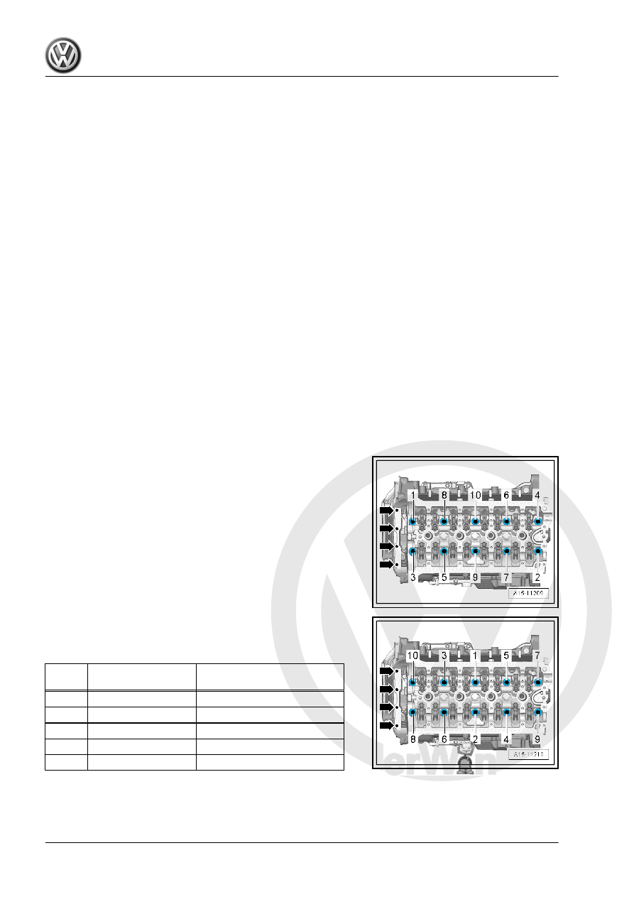
Loosening Cylinder Head
– Remove the bolts -arrows-.
– Loosen the cylinder head bolts in the sequence -1 to 10-.

Cylinder Head Tightening Sequence
– Tighten the cylinder head bolts in the sequence -1 to 10- as

follows.

Step

Bolts

Tightening Specification/Addi‐

tional Turn

1.

-1- through -10-

40 Nm

2.

-1- through -10-

Turn an additional 90°.

3.

-1- through -10-

Turn an additional 90°.

4.

Bolts -arrows-

4 Nm

5.

Bolts -arrows-

Turn an additional 90°.

Checking Cylinder Head for Distortion
– Check the cylinder head at several locations for distortion us‐

ing a Straight Edge - 500mm - VAS6075- and a feeler gauge.

♦ Maximum permissible distortion: 0.05 mm

1.2

Overview - Camshaft Housing

1 - Cylinder Head
2 - O-Ring

❑ Only installed on vehi‐

cles with the engine co‐

des CNTA, CXCA,

CXCB

❑ Replace after removing
❑ Coat with engine oil

3 - Cam Adjustment Actuator

❑ Only installed on vehi‐

cles with the engine co‐

des CNTA, CXCA,

CXCB

4 - Bolt

❑ 5 Nm
❑ Only installed on vehi‐

cles with the engine co‐

des CNTA, CXCA,

CXCB

5 - Ball Pin

❑ 9 Nm
❑ For engine cover

6 - O-Ring

❑ Replace after removing
❑ Coat with engine oil

7 - Plug
8 - O-Ring

❑ Replace after removing
❑ Coat with engine oil

9 - Camshaft Position Sensor

3 - G300-

❑ Overview. Refer to 

⇒ “1.1 Overview - Ignition System”, page 356

 .

10 - Bolt

❑ Tightening specification. Refer to 

⇒ “1.1 Overview - Ignition System”, page 356

 .

11 - Oil Separator

❑ Removing and installing. Refer to 

⇒ “3.2 Oil Separator, Removing and Installing”, page 196

 .

Pro

te

c

t

ed

  b

y

  co

p

y

rig

h

t. 

C

o

p

y

in

g

  fo

r 

pr

iv

a

t

e

 o

r

 c

o

m

m

e

r

c

ia

l 

p

u

rp

o

s

e

s

,

 i

n

 p

a

rt

o

r i

n

 w

h

o

le

, 

is

 n

o

t

 p

e

r

m

it

t

e

d

 u

n

l

e

s

s

 a

ut

ho

r

i

s

ed

 b

y

 V

olk

sw

a

ge

n AG

.


V

olk

s

w

a

g

en

 AG do

es 

n

ot g

uar

ante

e

 or a

c

c

ep

t

 a

ny


li

a

b

i

li

t

y

 w

ith

 r

e

s

p

e

c

t

 t

o


th

e

 c

o

rr

e

c

t

n

e

s

s


o

f

in

fo

r

m

a

tio

n

 in

 th

is

 d

o

c

um

en

t.

C

o

py

rig

ht b

y


V

olk

sw

a

ge

n


A

G.

12 - Bolt

❑ Tightening specification and sequence. Refer to

⇒ Fig. ““Vacuum Pump - Tightening Specifications”“ , page 94

 .

13 - Seal

❑ Replace after removing

14 - Vacuum Pump

❑ Removing and installing. Refer to 

⇒ “1.4 Vacuum Pump, Removing and Installing”, page 100

 .

15 - Bolt

❑ Tightening specification. Refer to 

⇒ Fig. ““Vacuum Pump - Tightening Specifications”“ , page 94

 .

16 - Seal

❑ Replace after removing

17 - O-Ring

❑ Replace after removing
❑ Coat with engine oil

18 - Camshaft Position Sensor - G40-

❑ Overview. Refer to 

⇒ “1.1 Overview - Ignition System”, page 356

 .

19 - Bolt

❑ Tightening specification. Refer to 

⇒ “1.1 Overview - Ignition System”, page 356

 .

20 - Bolt

❑ 9 Nm

21 - Bracket

❑ For EVAP Canister Purge Regulator Valve 1 - N80-

Vacuum Pump - Tightening Specifications
Tighten with a new bolts as follows:

Step

Bolts

Tightening Specification/Additional

Turn

1.

-1- through -3-

Install hand-tight

2.

-1- through -3-

8 Nm

3.

-1- through -3-

180° additional turn

1.3

Cylinder Head, Removing and Installing

Special tools and workshop equipment required
♦ Engine Bung Set - VAS6122-
♦ Engine Support Bridge - 10-222A-
Removing

Caution

This procedure contains mandatory replaceable parts. Refer

to component overview prior to starting procedure.

Mandatory Replacement Parts
♦ Nuts - Turbocharger to Engine

♦ Seal - Turbocharger to Engine
♦ Bolts - Cylinder Head
♦ Gasket - Cylinder Head

Note

♦

Before installing the cylinder head the engine support and the

engine mount are temporarily re-installed because the eyes

from the engine support bridge are secure on the cylinder

head.

♦

When installing, secure all cable ties back to the same posi‐

tions.

♦

Close the open channels from the intake and exhaust tract with

suitable plugs from the Engine Bung Set - VAS6122- .

– Remove the camshafts. Refer to

⇒ “4.2 Camshaft, Removing and Installing”, page 136

 .

– Reinstall the engine support and engine mount and tighten the

bolts hand-tight.

– Disengage the Engine Support Bridge - 10-222A- spindles.
– Drain the coolant. Refer to

⇒ “1.3 Coolant, Draining and Filling”, page 217

 .

– Remove front exhaust pipe with catalytic converter. Refer to

⇒ “2.2 Catalytic Converter, Removing and Installing”,

page 349

 .

– Remove the Oxygen Sensor 1 before Catalytic Converter -

GX10- . Refer to

⇒ “8.2  Oxygen Sensor 1 before Catalytic Converter GX10 ,

Removing and Installing”, page 333

 .

– Remove the left and right bolts -arrow-.
– Unclip the air guide lower section -1- and remove.

– Loosen the hose clamp -2-, remove the air duct hose from the

charge air cooler.

– Seal the open lines and connections with clean plugs from the

Engine Bung Set - VAS6122- .


Content   ..  662  663  664  665   ..