Volkswagen Golf / Golf GTI / Golf Variant. Manual - part 663


  Index      Volkswagen     Volkswagen Golf / Golf GTI / Golf Variant - service repair manual 2013 year


Search            copyright infringement  


Content   ..  661  662  663  664   ..


Volkswagen Golf / Golf GTI / Golf Variant. Manual - part 663


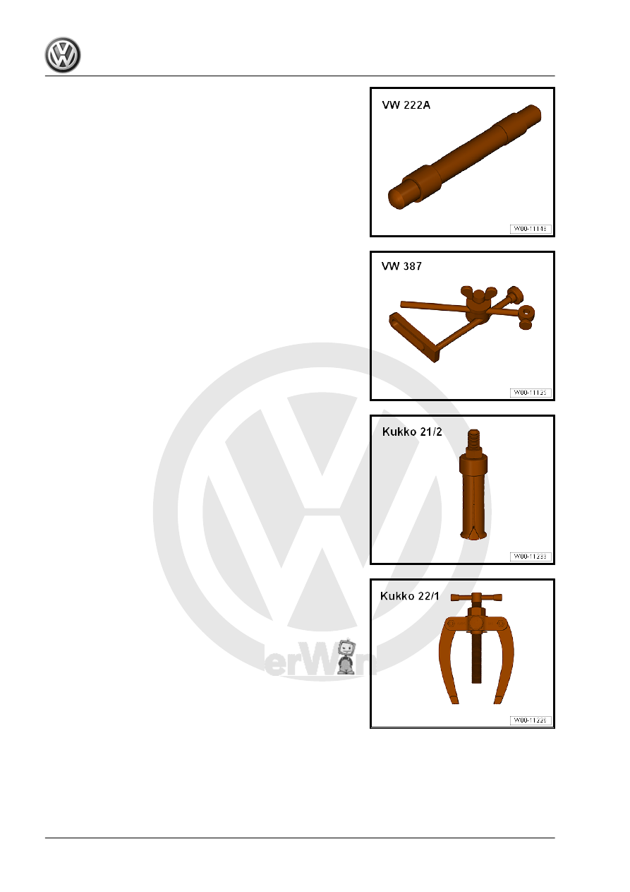
♦ Pilot Drift - VW222A-

♦ Dial Gauge Holder - VW387-

♦ Internal puller, for example Puller - Kukko Internal - 14-19mm

- 21/2-

♦ Counter-support for example Puller - Kukko Counterstay -

22/1-

♦ Flywheel Retainer - 3067-

♦ Engine Support Bridge - Spindle - 10-222A/11-
♦ Plastigage

®

Individual components of the Assembly Tool - T10531- :
♦ Counterhold Tool - T10531/1-
♦ Tensioning Pins - T10531/2-
♦ Turning Over Tool - T10531/3-
♦ Collar Nut - T10531/4-

15 – Cylinder Head, Valvetrain

1

Cylinder Head

⇒ “1.1 Overview - Cylinder Head”, page 90

 .

⇒ “1.2 Overview - Camshaft Housing”, page 93

 .

⇒ “1.3 Cylinder Head, Removing and Installing”, page 94

 .

⇒ “1.4 Vacuum Pump, Removing and Installing”, page 100

 .

⇒ “1.5 Compression Pressure, Checking”, page 101

 .

1.1

Overview - Cylinder Head

Note

Replace the cylinder head bolt.

Always replace self-locking nuts, bolts which have been tight‐

ened to tightening specifications as well as gaskets and O-

rings.

The plastic protectors installed to protect the open valves must

only be removed immediately before mounting the cylinder

head.

The engine oil and the coolant must be changed if the cylinder

head or the cylinder head gasket are being replaced.

1 - Alignment Pin
2 - Cylinder Head Gasket

❑ Replace after removing
❑ Installed position: the

part number faces the

cylinder head

3 - Cylinder Head

❑ Removing and instal‐

ling. Refer to

⇒ “1.3 Cylinder Head,

Removing and Instal‐

ling”, page 94

 .

❑ Check for distortion. Re‐

fer to

⇒ Fig. ““Checking Cylin‐

der Head for Distor‐

tion”“ , page 93

4 - Bolt

❑ 4 Nm + 90°
❑ Follow the procedure

when loosening. Refer

to

⇒ Fig. ““Loosening Cyl‐

inder Head”“ ,

page 92

❑ Follow the procedure

when tightening. Refer

to

⇒ Fig. ““Cylinder Head

Tightening Sequence”“ ,

page 92

❑ Replace after removing

5 - Heat Shield
6 - Bolt

❑ 9 Nm

7 - Bolt

❑ 9 Nm

8 - Heat Shield
9 - Bolt

❑ 9 Nm

10 - Bolt

❑ 9 Nm

11 - Connection

❑ For coolant hose

12 - O-Ring

❑ Coat with coolant
❑ Replace after removing

13 - Cylinder Head Bolt

❑ Follow the procedure when loosening. Refer to 

⇒ Fig. ““Loosening Cylinder Head”“ , page 92

❑ Follow the procedure when tightening. Refer to

⇒ Fig. ““Cylinder Head Tightening Sequence”“ , page 92

❑ Replace after removing


Content   ..  661  662  663  664   ..