Volkswagen Golf / Golf GTI / Golf Variant. Manual - part 654


  Index      Volkswagen     Volkswagen Golf / Golf GTI / Golf Variant - service repair manual 2013 year


Search            copyright infringement  


Content   ..  652  653  654  655   ..


Volkswagen Golf / Golf GTI / Golf Variant. Manual - part 654


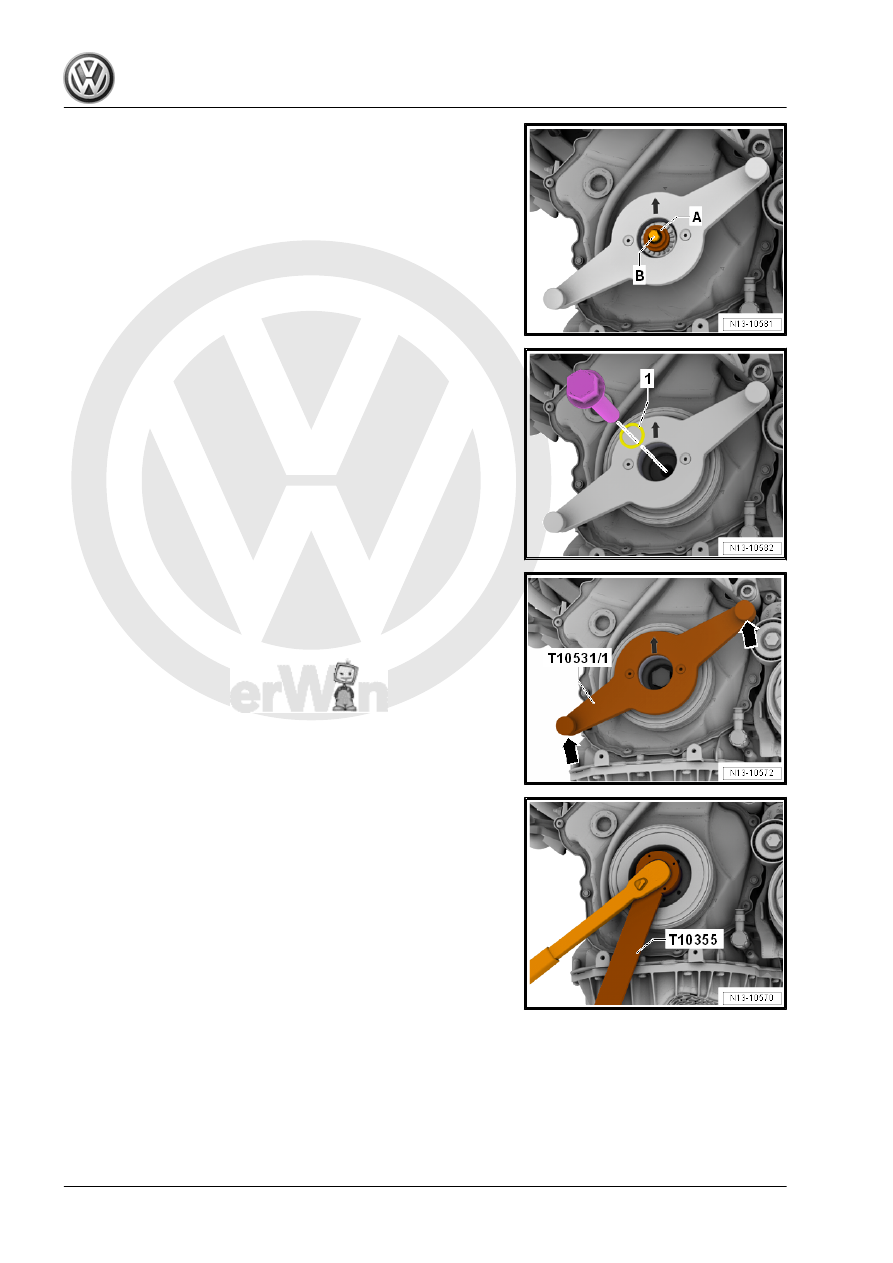
– Remove the Collar Nut -A- and loosen the tensioning bolt

-B-.

– Remove the Tensioning Pins and remove with Assembly Tool

- Turning Over Tool .

– Install a new vibration damper bolt with oiled O-ring -1- hand-

tight.

– Remove the knurled bolt -arrows- and remove the Counter‐

hold Tool - T10531/1- .

– Tighten vibration damper bolt using the Counterhold - Vibra‐

tion Damper - T10355- .

– Install new bolts -arrows-.

Assemble in reverse order of disassembly.
Tightening Specifications
♦ Refer to

⇒ “1.1 Overview - Cylinder Block, Belt Pulley Side”, page 44

 .

1.5

Auxiliary Components Bracket, Remov‐

ing and Installing

Special tools and workshop equipment required
♦ Shop Crane - Drip Tray - VAS6208-

Caution

This procedure contains mandatory replaceable parts. Refer

to component overview prior to starting procedure.

Mandatory Replacement Parts
♦ Bolts - Auxiliary Components Bracket
♦ O-ring - Engine Oil Cooler

Removing
– Drain the coolant. Refer to

⇒ “1.3 Coolant, Draining and Filling”, page 217

 .

– Remove the generator. Refer to ⇒  Electrical Equipment; Rep.

Gr.  27 ; Generator; Generator, Removing and Installing .

CAUTION

Danger of frostbite from refrigerant.
– Do not open the A/C system refrigerant circuit.

– Disconnect the connector -1- on the A/C Compressor Regu‐

lator Valve - N280- .

– Remove the bolts -arrows-.
– Remove the A/C compressor from the bracket with the refrig‐

erant hoses attached and tie up to the right side. Do not bend,

twist or stretch the refrigerant lines and hoses.

– Disconnect the connectors:
1 - For Oil Pressure Switch - F22- -2-
3 - For Reduced Oil Pressure Switch - F378- -4-
5 - For Piston Cooling Nozzle Control Valve - N522- -7-
– Remove the oil filter. Refer to ⇒ Maintenance ; Booklet  36.1 ;

Procedure Descriptions; Engine Oil, Draining, Replacing Oil

Filter, and Filling .

– Remove the bolt -1- for the oil dipstick guide tube.
– Unclip the guide tube from the upper cover for the timing chain

in the direction of the -arrow-.

Note

Ignore item -2-.

– Free up the wiring harness.

– Place the Shop Crane - Drip Tray - VAS6208- under engine.
– Remove the bolts -1 to 5-.
– Remove the sub-assembly bracket with the engine oil cooler

from the coolant pump housing.

– “Guide out” the accessories bracket between the intake mani‐

fold and engine support.

Installing
Install in reverse order of removal. Note the following:

Note

Replace the bolts that were tightened with an additional turn.

Replace the O-rings and seals.

– Coat the new O-rings -4- with coolant.
– Install the connection pieces -2- into the engine oil cooler -1-.
– Press the accessory assembly bracket with the engine oil

cooler -1- onto the connection, mount the bolts and tighten.

Refer to

⇒ Fig. ““Accessory Assembly Bracket - Tightening Specifica‐

tions and Tightening Sequence”“ , page 45

 .

– Install the A/C compressor. Refer to ⇒  Heating, Ventilation

and Air Conditioning; Rep. Gr.  87 ; A/C Compressor; Over‐

view - A/C Compressor Power Unit .

– Install the generator. Refer to ⇒  Electrical Equipment; Rep.

Gr.  27 ; Generator; Generator, Removing and Installing .

– Install the ribbed belt. Refer to

⇒ “1.2 Ribbed Belt, Removing and Installing”, page 46

 .

– Fill with coolant. Refer to 

⇒ page 218

 .

– Install the oil filter and then check the oil level. Refer to ⇒ Main‐

tenance ; Booklet  36.1 ; Procedure Descriptions; Engine Oil,

Draining, Replacing Oil Filter, and Filling .

Tightening Specifications
♦ Refer to

⇒ “1.1 Overview - Cylinder Block, Belt Pulley Side”, page 44

 .

♦ Refer to 

⇒ “2.1 Overview - Timing Chain Cover”, page 104

 .

♦ Install the oil filter and then check the oil level. Refer to ⇒ Main‐

tenance ; Booklet  36.1 ; Procedure Descriptions; Engine Oil,

Draining, Replacing Oil Filter, and Filling .

1.6

Engine Support, Removing and Instal‐

ling

Removing
Special tools and workshop equipment required
♦ Engine Support Bridge - Spindle - 10-222A/11-
– Remove the engine bracket. Refer to

⇒ “2.2 Engine Mount, Removing and Installing”, page 30

 .

– Lift the engine using the Engine Support Bridge - Spindle -

10-222A/11- -1- to dimension -a-.

• Dimension -a- = approximately 30 mm.


Content   ..  652  653  654  655   ..