Volkswagen Golf / Golf GTI / Golf Variant. Manual - part 653


  Index      Volkswagen     Volkswagen Golf / Golf GTI / Golf Variant - service repair manual 2013 year


Search            copyright infringement  


Content   ..  651  652  653  654   ..


Volkswagen Golf / Golf GTI / Golf Variant. Manual - part 653


Caution

This procedure contains mandatory replaceable parts. Refer

to component overview prior to starting procedure.

Mandatory Replacement Parts
♦ Bolts - Timing Chain Cover
♦ Bolt - Vibration Damper
♦ O-ring - Vibration Damper
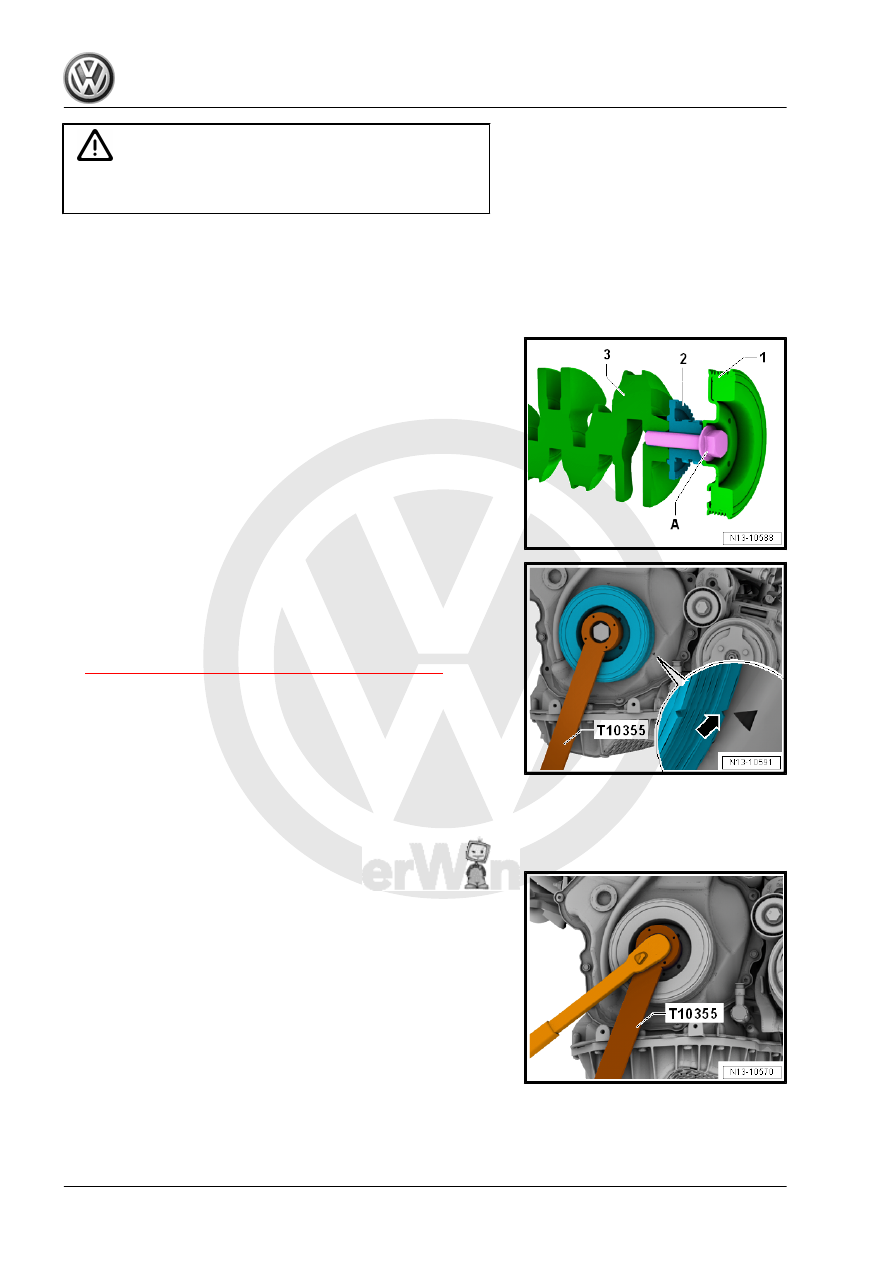
The vibration damper bolt -A- connects the vibration damper -1-

timing chain connection -2- and the crankshaft -3-. Secure the

chain sprocket as described as follows to the crankshaft, before

removing the vibration damper.

Remove Vibration Damper
– Remove the right wheel housing liner front section. Refer to ⇒ 

Body Exterior; Rep. Gr.  66 ; Wheel Housing Liner; Front

Wheel Housing Liner, Removing and Installing .

– Remove the ribbed belt. Refer to

⇒ “1.2 Ribbed Belt, Removing and Installing”, page 46

 .

– Remove the Locking Pin - T10060A- from the ribbed belt ten‐

sioner.

– Turn the vibration damper with the Counterhold - Vibration

Damper - T10355- to the Top Dead Center (TDC) point

-arrow-.

• The notch on the vibration damper must line up with the arrow

marking on the timing chain lower cover.

• The marking for the cover is located in the »four-o'clock posi‐

tion«.

– Loosen the vibration damper bolt approximately 

1

/2 turn, to do

this use the Counterhold - Vibration Damper - T10355- .

– If the vibration damper was turned, correct to TDC.

– Remove the bolts -arrows- for the timing chain cover. The bolts

must be replaced.

– Place the Counterhold Tool - T10531/1- as shown on the vi‐

bration damper and tighten hand-tight using the knurled bolt

-arrows-.

– Remove the vibration damper bolt completely.

– Check if the Assembly Tool - Turning Over Tool -A- can be

easily pushed over the clamping piece -B-. If necessary turn

the adjusting bolt -arrow-.

Note

Do not turn the tensioning bolt further, otherwise the Tensioning

Pins - T10531/2- becomes jammed when installing the crankshaft

– Install the Tensioning Pins - T10531/2- in the crankshaft and

with a 12 mm open end wrench -A- tighten hand-tight.

– Tighten the adjusting bolt -A- hand-tight, to secure the chain

sprocket to the crankshaft.

– Remove the knurled bolt -arrows-. Remove the Counterhold

Tool - T10531/1- and vibration damper -A-.

If Crankshaft is Turned without Vibration Damper
– Place the Assembly Tool - Turning Over Tool -A- on the ten‐

sioning pins and while doing so pay attention to the chain

sprocket tooth contour. The flat side of the top of the tool sits

in TDC.

– Tighten the Assembly Tool - Turning Over Tool with the Collar

Nut -B-.

– The crankshaft can now be turned on the hex fitting -arrow-.

Install Vibration Damper
– If necessary remove the Collar Nut -B- and the Assembly Tool

- Turning Over Tool -A- from the tensioning pins.

– Secure the vibration damper in TDC, while doing this pay at‐

tention to the tooth contour of the chain sprocket -arrow-.

– Place the Assembly Tool - Turning Over Tool -A- on the ten‐

sioning pins the at the same time the hex fitting points to the

vibration damper.

– Install the Collar Nut -B-, while doing this move the vibration

damper slightly back and forth, to check in the vibration damp‐

er is correctly in the tooth contour. Tighten the collar nut, until

the vibration damper can no longer be turned.

– Place the Counterhold Tool - T10531/1- as shown on the vi‐

bration damper and tighten hand-tight using the knurled bolt

-arrows-.


Content   ..  651  652  653  654   ..