Volkswagen Golf / Golf GTI / Golf Variant. Manual - part 652
13 – Crankshaft, Cylinder Block
1
Cylinder Block, Belt Pulley Side
⇒ “1.1 Overview - Cylinder Block, Belt Pulley Side”, page 44
⇒ “1.2 Ribbed Belt, Removing and Installing”, page 46
⇒ “1.3 Ribbed Belt Tensioner, Removing and Installing”,
page 47
⇒ “1.4 Vibration Damper, Removing and Installing”, page 47
⇒ “1.5 Auxiliary Components Bracket, Removing and Installing”,
page 53
⇒ “1.6 Engine Support, Removing and Installing”, page 55
1.1
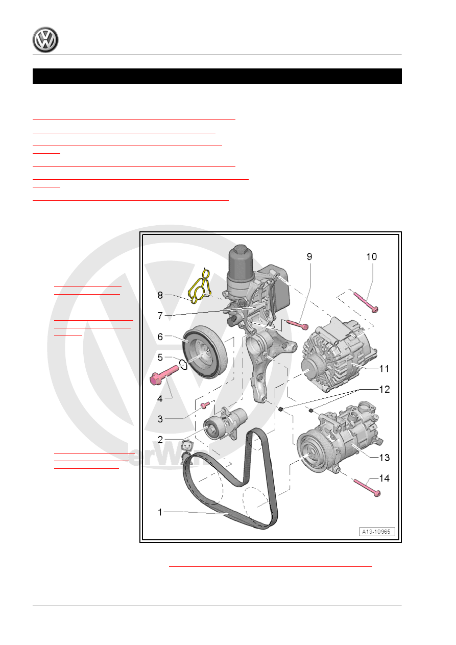
Overview - Cylinder Block, Belt Pulley Side
1 - Ribbed Belt
❑ Check for wear
❑ Do not kink
❑ Ribbed belt routing. Re‐
fer to
❑ Removing and instal‐
ling. Refer to
❑ When installing, make
sure it is seated correct‐
ly on the pulleys
2 - Ribbed Belt Tensioning
Damper
❑ To release tension on
ribbed belt, pivot using a
wrench.
❑ Secure using Locking
Pin - T10060A-
❑ Removing and instal‐
ling. Refer to
.
3 - Bolt
❑ 8 Nm + 45° turn
❑ Replace after removing
4 - Bolt
❑ 150 Nm + 90° turn
❑ Replace after removing
❑ Use the Counterhold -
Pulley - T10475- to loosen and tighten
❑ Removing and installing. Refer to
⇒ “1.4 Vibration Damper, Removing and Installing”, page 47
5 - O-Ring
❑ Not a replacement part; supplied with the bolt