Volkswagen Golf / Golf GTI / Golf Variant. Manual - part 647
 

  Index      Volkswagen     Volkswagen Golf / Golf GTI / Golf Variant - service repair manual 2013 year


Search            copyright infringement  


Content   ..  645  646  647  648   ..


Volkswagen Golf / Golf GTI / Golf Variant. Manual - part 647


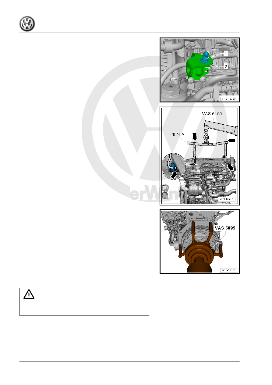
– Unclip the right engine cover mount -1-.

– Hook the Engine Sling - 2024A- to the engine and to the Shop

Crane - VAS6100- .

– To be aligned to the center of gravity of the engine assembly,

the hole rails must be inserted as shown in the illustration.

– Secure the mounting hooks and pins on the engine support

bridge using securing pins -arrows-.

– Lower the engine from the Engine and Gearbox Jack -

VAS6931- using the Shop Crane - VAS6100- .

– Remove the transmission alignment sleeve and secure the

transmission side of the engine on the Engine And Transmis‐

sion Holder - VAS6095- .

1.4

Engine, Installing

Caution

This procedure contains mandatory replaceable parts. Refer

to component overview prior to starting procedure.

Mandatory Replacement Parts
♦ Bolts - Transmission Mount
♦ Bolts - Engine to Transmission

Tightening Specifications

Note

♦

The tightening specifications apply only to lightly greased,

oiled, phosphated or blackened nuts and bolts.

♦

Additional lubricants, such as engine or transmission oil are

permissible, although lubricants containing graphite are not.

♦

Do not use any ungreased parts.

♦

Tightening specification tolerance: ±15%.

Component

Nm

Bolts and nuts

M6

10


M7

15


M8

20


M10

40


M12

65

♦ Refer to 

⇒ “2.1 Overview - Subframe Mount”, page 29

 .

♦ Securing engine to transmission. Refer to ⇒  Rep. Gr.  34 ;

Transmission, Removing and Installing; Transmission Tight‐

ening Specifications .

Procedure

Note

♦

Replace the bolts that were tightened with an additional turn.

♦

Replace the self-locking nuts and bolts, sealing rings, seals

and O-rings.

♦

The hose connections as well as the air guide pipes and hoses

must be free of oil and grease before installing.

♦

Secure hose connections with standard production clamps.

Refer to the Parts Catalog.

♦

During installation, all cable ties must be installed at the same

location.

– Install intermediate plate. Refer to

⇒ Fig. ““Installing Intermediate Plate”“ , page 58

 .

Note

The illustration shows a vehicle with DSG

®

 transmission.

– If the alignment sleeves -A- for centering the engine and trans‐

mission are missing inside the cylinder block, then install the

sleeves.

Vehicles with a Manual Transmission
– If a needle bearing is installed in the crankshaft, remove the

needle bearing. Refer to

⇒ “3.4 Crankshaft Needle Bearing, Replacing”, page 65

 .

– If the clutch release bearing is worn, replace it. Refer to ⇒ 

Manual Transmission; Rep. Gr.  30 ; Clutch Mechanism;

Clutch Release Mechanism, Servicing .

– Lightly lubricate the transmission input shaft splines. Refer to

the Parts Catalog.

– Check the clutch plate alignment.
Vehicles with DSG

®

 Transmission

– If no needle bearing is installed in crankshaft, install needle

bearing. Refer to ⇒  Engine Mechanical, Fuel Injection and

Ignition; Rep. Gr.  13 ; Crankshaft; Crankshaft Needle Bearing,

Replacing .

Continuation for All Vehicles
– Attach transmission to engine.
– Install the starter. Refer to ⇒  Electrical Equipment; Rep. Gr. 

27 ; Starter; Starter, Removing and Installing .

– Guide the engine/transmission assembly into the body.

– Install the bolts -arrows- for the engine mount by hand all the

way.

– Install the bolts -arrows- for the transmission mount by hand

until it is in position.

Note

Only tighten the bolts to the specification when installing the sub‐

frame mount. Refer to

⇒ “2.1 Overview - Subframe Mount”, page 29

 .

– Remove the Engine/Gearbox Jack - Engine Support -

T10359A- from the engine.

– Install drive axles. Refer to ⇒  Suspension, Wheels, Steering;

Rep. Gr.  40 ; Drive Axle; Drive Axle, Removing and Installing .

Vehicles with a Manual Transmission
– Install the clutch slave cylinder. Refer to ⇒  Controls, Housing;

Rep. Gr.  34 ; Selector Mechanism; Selector Mechanism, Re‐

moving and Installing .

– Install the cables with the cable bracket. Refer to ⇒  Manual

Transmission; Rep. Gr.  30 ; Clutch Mechanism; Component

Location Overview - Clutch Mechanism .

Vehicles with DSG

®

 Transmission

– Install and adjust the selector lever cable. Refer to ⇒  Rep. Gr. 

34 ; Selector Mechanism; Overview - Selector Mechanism .

Continuation for All Vehicles
– Install the Air Conditioning (A/C) compressor. Refer to ⇒ 

Heating, Ventilation and Air Conditioning; Rep. Gr.  87 ; A/C

Compressor; Overview - A/C Compressor Power Unit .

– Install the ribbed belt. Refer to

⇒ “1.2 Ribbed Belt, Removing and Installing”, page 46

 .

– Adjust the subframe mount. Refer to

⇒ “2.6 Subframe Mount, Adjusting”, page 36

 .

– Install the battery tray. Refer to ⇒  Electrical Equipment; Rep.

Gr.  27 ; Battery; Overview - Battery .

– For the electrical connections and wiring routing. Refer to ⇒ 

Electrical Equipment; Rep. Gr.  97 ; Relay Carriers, Fuse Pan‐

els and E-Boxes; Component Location Overview - Relay Car‐

riers, Fuse Panels and E-Boxes and ⇒ Wiring diagrams,

Troubleshooting & Component locations.

– Install the air filter housing. Refer to

⇒ “3.2 Air Filter Housing, Removing and Installing”,

page 294

 .

– Install the engine cover. Refer to

⇒ “3.1 Engine Cover, Removing and Installing”, page 38

 .

– Check the oil level.
– Attach the coolant hoses to the heater core. Refer to

⇒ Fig. ““Connect the Coolant Hose to the Coupling”“ ,

page 245

 .

– Fill with coolant. Refer to 

⇒ page 218

 .

Note

Do not reuse used coolant.


Content   ..  645  646  647  648   ..