Volkswagen Golf / Golf GTI / Golf Variant. Manual - part 645


  Index      Volkswagen     Volkswagen Golf / Golf GTI / Golf Variant - service repair manual 2013 year


Search            copyright infringement  


Content   ..  643  644  645  646   ..


Volkswagen Golf / Golf GTI / Golf Variant. Manual - part 645


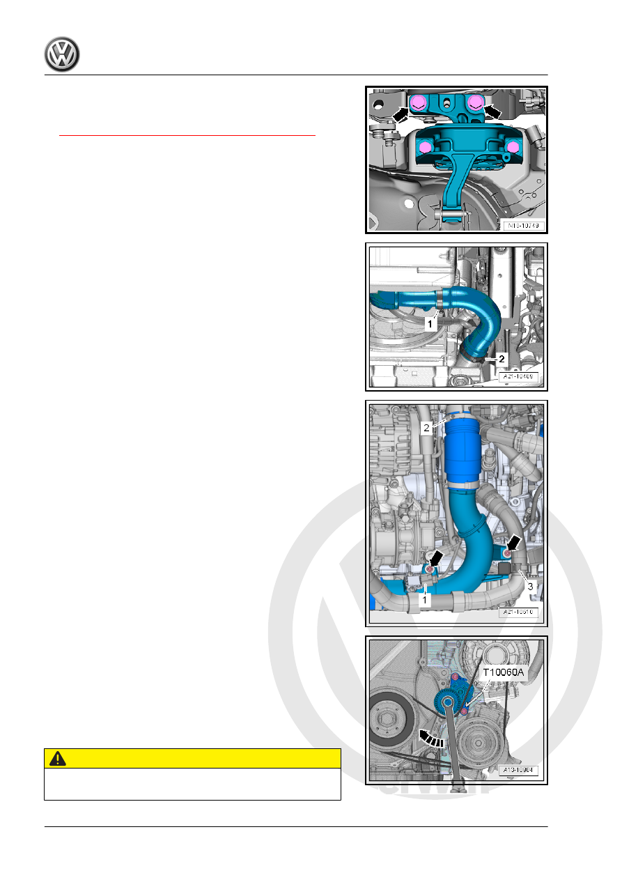
– Remove the bolts -arrows- for the engine mount (about two

turns).

– Remove the fan shroud. Refer to

⇒ “4.5 Fan Shroud, Removing and Installing”, page 249

 .

– Open the clamp -1 and 2- and remove the air duct hose.
– Seal the open lines and connections with clean plugs from the

Engine Bung Set - VAS6122- .

– Free up the coolant hose -3-.
– Remove the bolts -arrows-.
– Loosen the hose clamp -2-.
– Disconnect the connector -1- on the Charge Air Pressure Sen‐

sor - G31- .

– Remove the right air guide pipe.
– Before removing the ribbed belt, mark the running direction

with chalk or a felt-tip pen for reinstallation.

– Pivot the tensioner clockwise in direction of -arrow- to release

the tension on the ribbed belt.

– Remove the ribbed belt from the A/C compressor ribbed belt

pulley and release the tension on the tensioning device. If

necessary, remove the Locking Pin - T10060A- .

CAUTION

Danger of frostbite from refrigerant.
– Do not open the A/C system refrigerant circuit.

– Disconnect the connector -1- on the A/C Compressor Regu‐

lator Valve - N280- .

– Remove the bolts -arrows-.
– Remove the A/C compressor from the bracket with the refrig‐

erant hoses attached and tie up to the right side. While doing

so, do not bend, twist or stretch the refrigerant lines and hoses.

– Remove the left and right drive axles from the flange shafts.

Refer to ⇒  Suspension, Wheels, Steering; Rep. Gr.  40 ; Drive

Axle; Drive Axle, Removing and Installing .

– Tie up the drive axles to the rear.

Note

Be careful not to damage the protective coating on the drive axle.

– Loosen the clamping sleeve -arrow- and push it toward the

rear.

– Remove the catalytic converter with the front exhaust pipe.

– Remove bolt -arrow-, push the bracket for the wiring harness

aside.

– Install the Adapter - T10359/3- , as shown in the illustration,

on the Engine/Gearbox Jack - Engine Support - T10359A- .

– Tighten Engine/Gearbox Jack - Pin - T10359/2- with support

element -A- from the Transmission Support - 3282- to the en‐

gine bracket.

– Place the Engine/Gearbox Jack - Engine Support - T10359A-

in the Engine and Gearbox Jack - VAS6931- .

– Install the Engine/Gearbox Jack - Engine Support - T10359A-

on the cylinder block. Fasten the bolt -A- with the spacer

sleeve on the cylinder block. Tightening specification 20 Nm.

– Secure the engine with the support element -B- and lift the

engine with the transmission.

– Remove the engine mount bolts -arrows- completely.

– Remove the transmission mount bolts -arrows- completely.
– Carefully lower the engine/transmission sub-assembly in di‐

rection of -arrow 1-.

– Carefully guide the engine/transmission sub-assembly for‐

ward and out to the left in direction of -arrow 2-.

1.2

Engine and Transmission, Separating

⇒ “1.2.1 Engine and Transmission, Separating, Vehicles with

Manual Transmission”, page 19

 .

⇒ “1.2.2 Engine and Transmission, Separating, Vehicles with

DSG® Transmission”, page 21

 .

1.2.1

Engine and Transmission, Separating,

Vehicles with Manual Transmission

Special tools and workshop equipment required
♦ Engine Support Bridge - Additional Hooks (2 pc.) - 10-222A/

2-

♦ Shop Crane - VAS6100-
♦ Transmission Lift Hook - T40013-
♦ Engine/Gearbox Jack - Engine Support - T10359A-

Caution

This procedure contains mandatory replaceable parts. Refer

to component overview prior to starting procedure.

Mandatory Replacement Parts
♦ Bolts - Transmission Mount


Content   ..  643  644  645  646   ..