Volkswagen Golf / Golf GTI / Golf Variant. Manual - part 644


  Index      Volkswagen     Volkswagen Golf / Golf GTI / Golf Variant - service repair manual 2013 year


Search            copyright infringement  


Content   ..  642  643  644  645   ..


Volkswagen Golf / Golf GTI / Golf Variant. Manual - part 644


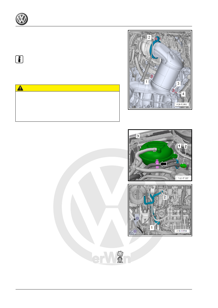
– Remove the connectors -1 and 2- from the holder and discon‐

nect them. Then free up the electric wires.

– Remove the bolt -2- and the screw-type clamp.
– Remove the nuts -1 and 3-.

Note

The installed position is shown in the illustration with the en‐

gine removed.

Ignore -4-.

CAUTION

Fuel system is under pressure.
Risk of injury from fuel spraying out.
– Wear protective eyewear.
– Wear safety gloves.
– Reduce the pressure: Lay clean cloths around the connec‐

tion location and carefully open the connection point.

– Disconnect the hose couplings -1 and 2-. Refer to ⇒  Fuel

Supply System; Rep. Gr.  20 ; Connector Couplings; Connec‐

tor Couplings, Separating . Loosen the hose clamp from the

expansion tank -3-.

– Loosen the clamps -1 and 2- and remove the coolant hoses.

– Lift the clamp -arrow- and remove the upper left coolant hose

from the radiator.

Note

Use the Pry Lever - 80-200- for removing the spiral clips in the

following procedure.

– Disconnect the connector -1- from the Engine Control Module

- J623- . Refer to

⇒ “6.1  Engine Control Module J623 , Removing and Instal‐

ling”, page 321

 .

– Disconnect the connectors -2 and 3- from the bracket.
– Free up the wires.

– Release the retainers in direction of -arrows-, and remove the

cover -1- from the engine compartment E-box.

– Open the retainers with a screwdriver in direction of -arrow-,

remove the cover -1- for the engine compartment E-box up‐

ward.

– Remove the nut -arrow-, disconnect and free up the wires.

Vehicles with a Manual Transmission
– Disconnect the connector -2-.
– Push back the B+ terminal protector -1- and disconnect the B

+ wire from the starter solenoid switch.

– Remove the nut -3- and remove the ground wire.

Note

Depending on the version the ground cable is attached to the

starter bolt.

– Disconnect the left front connectors from the transmission:
1 - For Transmission Neutral Position Sensor - G701-
2 - For Back-Up Lamp Switch - F4-
– Remove the gearshift and the selector lever cable from the

transmission, remove the cable mounting bracket and move it

to the side with the cables. Refer to the ⇒  Controls, Housing;

Rep. Gr.  34 ; Selector Mechanism; Selector Mechanism, Re‐

moving and Installing repair manual.

– Clamp the hose/line assembly -A- to the slave cylinder with

the Hose Clamps - Up To 25mm - 3094- .

– Pull hose/line assembly clip -arrow- out as far as stop.
– Remove pipe/hose line assembly from the slave cylinder ven‐

tilator.

Vehicles with DSG

®

 Transmission

– Selector lever cable from the transmission and pull it out of the

cable bracket. Refer to the ⇒  Controls, Housing; Rep. Gr.  34 ;

Selector Mechanism; Selector Mechanism, Removing and In‐

stalling repair manual.

– Disconnect the connector -2-.
– Push back the B+ terminal protector -1- and disconnect the B

+ wire from the starter solenoid switch.

– Remove the nut -3- and remove the ground wire.

Note

Depending on the version the ground cable is attached to the

starter bolt.

– To discharge static electricity, touch vehicle ground with hand

(without gloves).

– Do not touch contacts in transmission connector with hands.
– Disconnect the connector -4- for the DSG Transmission Me‐

chatronic - J743- , by turning screw connection counterclock‐

wise.

Continuation for All

– Remove the bolts -arrows- for the transmission (about 2 turns).


Content   ..  642  643  644  645   ..