Volkswagen Golf / Golf GTI / Golf Variant. Manual - part 646


  Index      Volkswagen     Volkswagen Golf / Golf GTI / Golf Variant - service repair manual 2013 year


Search            copyright infringement  


Content   ..  644  645  646  647   ..


Volkswagen Golf / Golf GTI / Golf Variant. Manual - part 646


♦ Bolts - Engine to Transmission
Procedure
• Engine/transmission assembly removed and secured on the

Engine/Gearbox Jack - Engine Support - T10359A- .

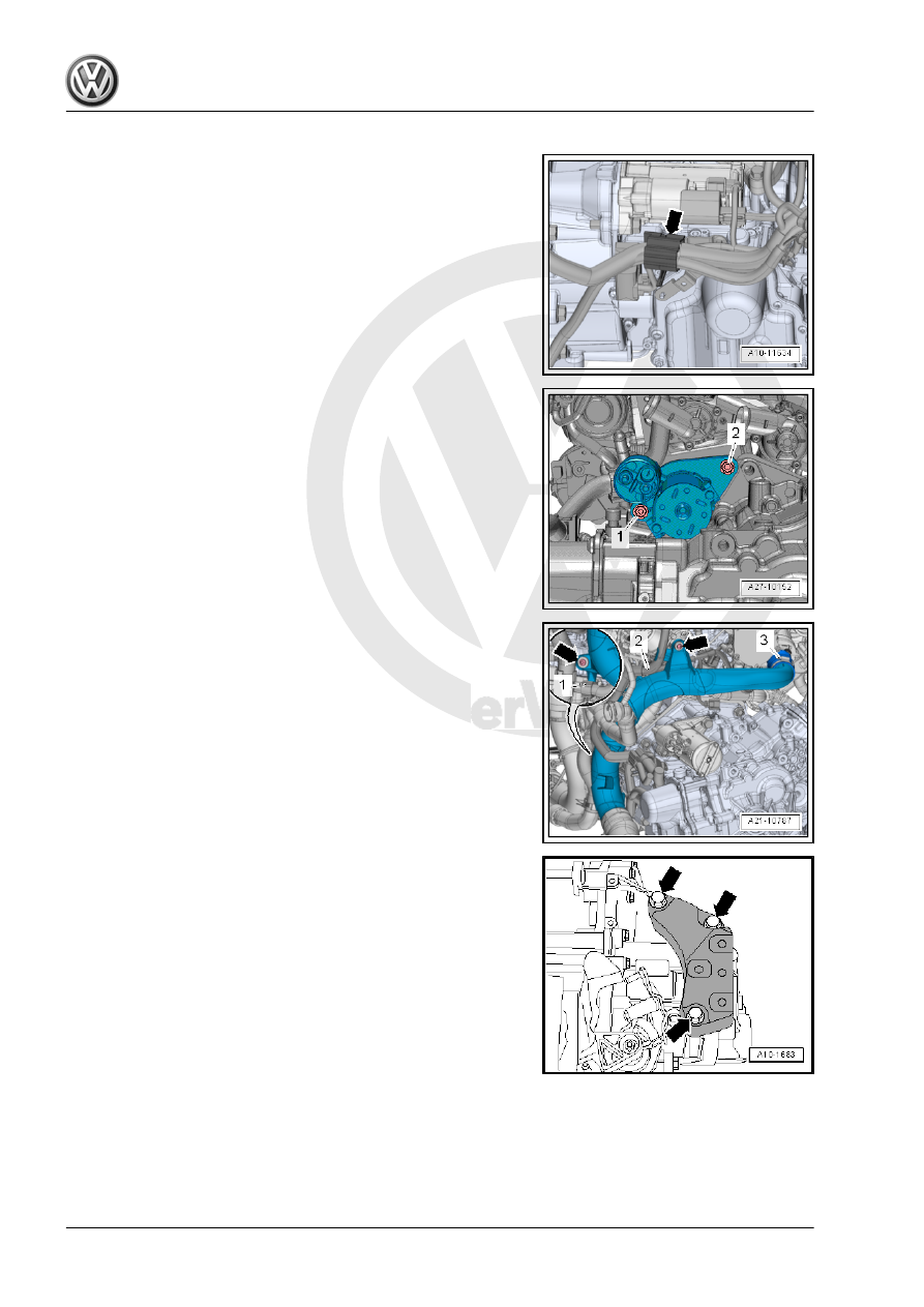
– Free up the wire on the bracket -arrow-.

– Remove the bolts -1 and 2- and then remove the starter from

the transmission.

– Free up the wiring harness -1 and 2- from the air guide pipe.

– Loosen the screw-type clamp -3-.
– Remove the bolts -arrows- and remove the air guide pipe.

– Remove bolts -arrows- and remove the transmission support.

– Install the Transmission Lift Hook - T40013- on the transmis‐

sion and close locking device.

– Engage the Shop Crane - VAS6100- with Engine Support

Bridge - Additional Hooks (2 pc.) - 10-222A/2- on the trans‐

mission lift hook.

Note

Ignore items -4, 5, and A-.

– Remove the bolts -1, 2, 3, 6, 7, 8, and 9- connecting the trans‐

mission to the engine.

– Remove the transmission from the engine.

1.2.2

Engine and Transmission, Separating,

Vehicles with DSG

®

 Transmission

Special tools and workshop equipment required
♦ Engine Support Bridge - Additional Hooks (2 pc.) - 10-222A/

20-

♦ Hooks Engine Sling - Engine Bracket - 2024A/1- from the En‐

gine Sling - 2024A-

♦ Shop Crane - VAS6100-
♦ Engine Bung Set - VAS6122-
♦ Hose Clamps - Up To 25mm - 3094-

Caution

This procedure contains mandatory replaceable parts. Refer

to component overview prior to starting procedure.

Mandatory Replacement Parts
♦ Bolts - Engine to Transmission

Procedure
• Engine/transmission assembly removed and secured on the

Engine Support - T10497- .

– Remove the starter. Refer to ⇒  Electrical Equipment; Rep. Gr. 

27 ; Starter; Starter, Removing and Installing .

– Remove the nuts -arrows-, and remove the front bracket from

the transmission fluid pan.

Note

The threaded bolts are welded to the front of the oil pan.

– Disconnect the connector -2-.

Note

Place a cleaning cloth underneath, to catch coolant leaking out.

– Loosen the hose clamps -arrows-, remove the coolant hoses

from the transmission fluid cooling circuit.

– Remove the bolts -1- and set aside the Transmission Coolant

Valve - N488- .

– Seal the open lines and connections with clean plugs from the

Engine Bung Set - VAS6122- .

Note

Ignore Hose Clamps - Up To 25mm - 3094- .

– Attach the Engine Sling - 2024A- hooks to the transmission

lifting eyes and secure it with the securing pin -arrow-.

– Hook the Shop Crane - VAS6100- with the Engine Support

Bridge - Special Hook (2 pc.) - 10-222A/20- on the Engine

Sling - Engine Bracket - 2024A/1- .

– Remove the bolts -1 to 8- for the transmission/engine connec‐

tion.

Note

Ignore item -A-.

– Remove the transmission from the engine.

1.3

Engine, Securing on Engine and Trans‐

mission Holder

Special tools and workshop equipment required
♦ Engine Sling - 2024A-
♦ Shop Crane - VAS6100-
♦ Engine And Transmission Holder - VAS6095-
Procedure
• The transmission is separated from the engine. Refer to

⇒ “1.2 Engine and Transmission, Separating”, page 19

 .

– Unlock the retaining tab in direction of -arrow-, remove the left

engine cover mount -1-.


Content   ..  644  645  646  647   ..