Volkswagen Golf / Golf GTI / Golf Variant. Manual - part 490


  Index      Volkswagen     Volkswagen Golf / Golf GTI / Golf Variant - service repair manual 2013 year


Search            copyright infringement  


Content   ..  488  489  490  491   ..


Volkswagen Golf / Golf GTI / Golf Variant. Manual - part 490


1.9

Bearing Bushing, Removing and Instal‐

ling

Removing
Disconnect the battery ground cable. Refer to ⇒  Electrical Equip‐

ment; Rep. Gr.  27 ; Battery; Battery, Disconnecting and Con‐

necting .
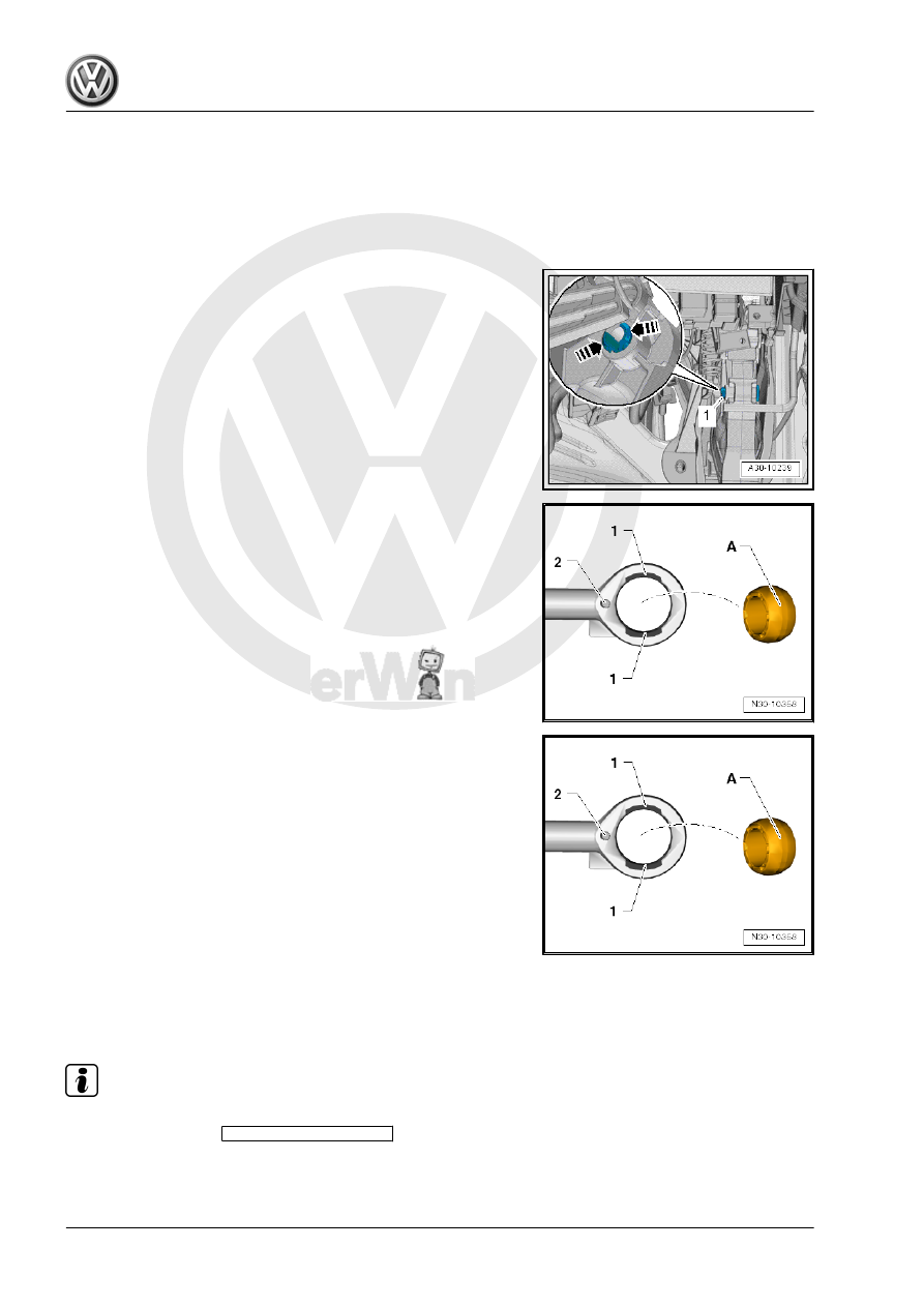
– Press together the retainers in the direction of -arrows- and

remove the studs -1- to the right side.

– Turn the valve fitter such that the openings -1- or pin -2- are

visible.

The openings -1- and the pin -2- face in the same direction.
– Remove the bearing bushing -A- from the openings -1-.

Installing
– Turn the valve fitter such that the openings -1- or pin -2- are

visible.

The openings -1- and the pin -2- face in the same direction.
– Fit the bearing bushing -A- in the openings -1- and rotate into

place.

– Use a new mounting pin to connect the valve fitter/clutch mas‐

ter cylinder to the clutch pedal.

– Connect the battery. Refer to ⇒  Electrical Equipment; Rep.

Gr.  27 ; Battery; Battery, Disconnecting and Connecting .

1.10

Clutch Master Cylinder, Removing and

Installing

Removing

Note

Before replacing the clutch master cylinder due to an assumed

defect, perform the 

Guided Fault Finding

 Vehicle Diagno‐

sis Tester first.

When working inside the footwell, cover the carpet with cloths

to protect it from leaking brake fluid.

– Remove the bracket. Refer to

⇒ “1.8 Mounting Bracket, Removing and Installing”, page 28

 .

– Remove the Clutch Position Sensor - G476- . Refer to

⇒ “1.15  Clutch Position Sensor G476 , Removing and Instal‐

ling”, page 37

 .

– Release retainers in the direction of -arrows- and remove

mounting pin -2-.

– Remove clutch master cylinder -1-.
Installing
Install in reverse order of removal. Note the following:
Replace mounting pin after removing.
– Install the bracket. Refer to

⇒ “1.8 Mounting Bracket, Removing and Installing”, page 28

 .

– Install the Clutch Position Sensor - G476- . Refer to

⇒ “1.15  Clutch Position Sensor G476 , Removing and Instal‐

ling”, page 37

 .

1.11

Clutch Slave Cylinder with Release

Bearing, Removing and Installing

Special tools and workshop equipment required
♦ Torque Wrench 1331 5-50Nm - VAG1331-

Note

The clutch slave cylinder and the release bearing are a single

unit and are replaced together.

Pay attention to the thread pitch on the bolts when cleaning

the threaded hole in the clutch housing.

Removing
• Transmission is removed.
– Open the clip -2- with a screwdriver or a pointed tool and re‐

move bleeder -4- from clutch slave cylinder -1-.

– Remove the bolts -arrows-.
– Remove the clutch slave cylinder together with the release

bearing -A-.

Installing
Install in the reverse order of removal while noting the following:
• Tighten the slave cylinder bolts in small increments only.
Otherwise, there is the danger that the tabs with the fastening

holes could break off.

– Check the O-ring -3- on the clutch slave cylinder for damage.
– Push the bleeder -4- onto the clutch slave cylinder connection

-1- until the clip -2- clicks into place.

– To check, pull on the bleeder.
– Install the transmission. Refer to

⇒ “2.2 Transmission, Installing”, page 92

 .

– Bleed the clutch mechanism. Refer to

⇒ “1.16 Clutch Mechanism, Bleeding”, page 37

 .

Tightening Specifications
♦ Clutch slave cylinder with release bearing to transmission.

Refer to

⇒ “1.4 Overview - Clutch Release Mechanism”, page 21

 .

1.12

Clutch Mechanism Lines, Removing

and Installing

Special tools and workshop equipment required
♦ Hose Clamps - Up To 25mm - 3094-
Removing
– Disconnect the battery ground cable. Refer to ⇒  Electrical

Equipment; Rep. Gr.  27 ; Battery; Battery, Disconnecting and

Connecting .

– Remove the air filter housing if the lines are not accessible.
Vehicles with a Turbo Diesel Engine
– Refer to ⇒  Engine Mechanical, Fuel Injection and Glow Plug;

Rep. Gr.  23 ; Air Filter; Air Filter Housing, Removing and In‐

stalling .

Vehicles with a Gasoline Engine
– Refer to ⇒  Engine Mechanical, Fuel Injection and Ignition;

Rep. Gr.  24 ; Air Filter; Air Filter Housing, Removing and In‐

stalling .

Continuation for All
– Remove the battery and the battery tray. Refer to ⇒  Electrical

Equipment; Rep. Gr.  27 ; Battery; Battery, Disconnecting and

Connecting .

Caution

Danger of leaking brake fluid.

♦ Be careful not to get any brake fluid on the longitudinal

member or on the transmission when performing the fol‐

lowing work. If it does, clean the area thoroughly.

♦ Place a lint-free cloth under the clutch master cylinder.

– Unclamp the supply hose -2- to the clutch master cylinder with

a -3094- .

Note

A slight deformation of the supply hose remains after the

-3094- have been unclamped.

The supply hose is therefore not defective.

After removing the -3094- , the supply hose must be formed

back into its original shape.

– Remove clip for hose/line assembly -1- all the way and remove

hose/line assembly.

– Seal off openings.

– Remove the clip -arrow- all the way and then remove the hose/

line assembly -A- from the bleeder.

Ignore item -B-.
– Seal the open lines and connections with clean plugs if nec‐

essary from the -VAS6122- .

– Free up the hose/line assembly and remove it.
Installing
Install in reverse order of removal. Note the following:

– Connect hose/line assembly -1- with clutch master cylinder.
– Pull on the line to make sure it is secure.


Content   ..  488  489  490  491   ..