Volkswagen Golf / Golf GTI / Golf Variant. Manual - part 491
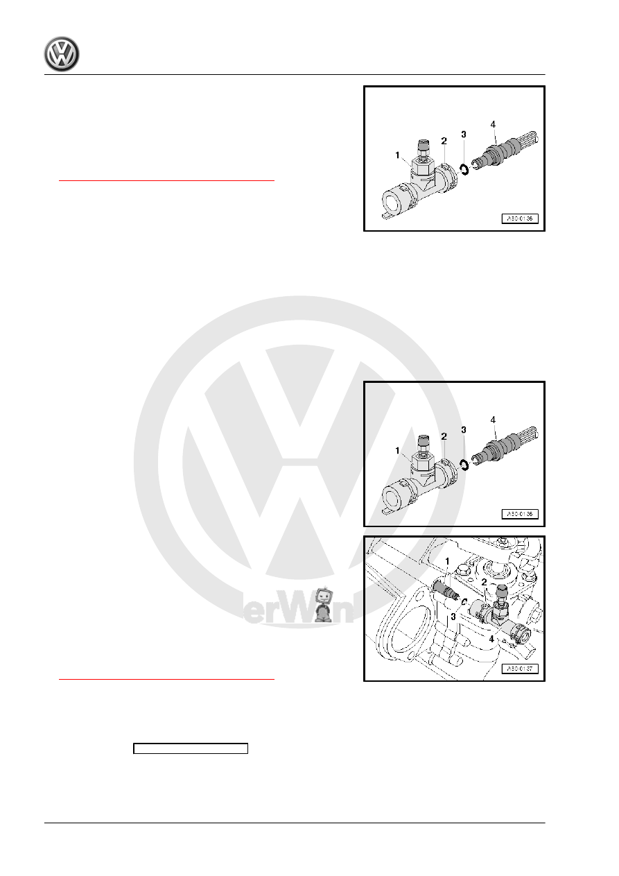
– Push the hose/line assembly -4- with the O-ring -3- onto the
bleeder connection -1- until the clip -2- audibly locks into place.
– Pull on the line to make sure it is secure.
• After removing the -3094- , the return hose -2- (⇒ previous
illustration) must be formed back into its original shape.
– Bleed the clutch mechanism. Refer to
⇒ “1.16 Clutch Mechanism, Bleeding”, page 37
– Install the air filter housing.
Vehicles with a Turbo Diesel Engine
– Refer to ⇒ Engine Mechanical, Fuel Injection and Glow Plug;
Rep. Gr. 23 ; Air Filter; Air Filter Housing, Removing and In‐
stalling .
Vehicles with a Gasoline Engine
– Refer to ⇒ Engine Mechanical, Fuel Injection and Ignition;
Rep. Gr. 24 ; Air Filter; Air Filter Housing, Removing and In‐
stalling .
Continuation for All
– Install the battery tray, battery and the battery cover. Refer to
⇒ Electrical Equipment; Rep. Gr. 27 ; Battery; Battery, Dis‐
connecting and Connecting .
1.13
Bleeder, Removing and Installing
Hose/Line Assembly or Pipe -4- on Bleeder -1-, Removing and
Installing
– To remove, release the clip -2- with a screwdriver or a pointed
tool and pull off hose/line assembly or pipe -4- from the bleeder
-1-.
– To install, press hose/line assembly or pipe with new O-ring
-3- onto the bleeder connection, until clip audibly engages.
– Pull on the line to make sure it is secure.
Removing and Installing the Bleeder -4- from the Clutch Slave
Cylinder
– To remove, release the clip -2- with a screwdriver or a pointed
tool and remove the bleeder -4- from the clutch slave cylinder
-1-.
– To install, check the O-ring -3- on the clutch slave cylinder.
Press in the bleeder at the clutch slave cylinder connector until
the clip -2- engages audibly.
– To check, pull on the bleeder.
– Bleed the clutch mechanism. Refer to
⇒ “1.16 Clutch Mechanism, Bleeding”, page 37
1.14
Clutch Master and Clutch Slave Cylin‐
der, Checking
Before replacing the clutch master cylinder due to an assumed
defect, perform the
Guided Fault Finding
with the Vehicle Di‐
agnosis Tester first.