Volkswagen Golf / Golf GTI / Golf Variant. Manual - part 489
Installing
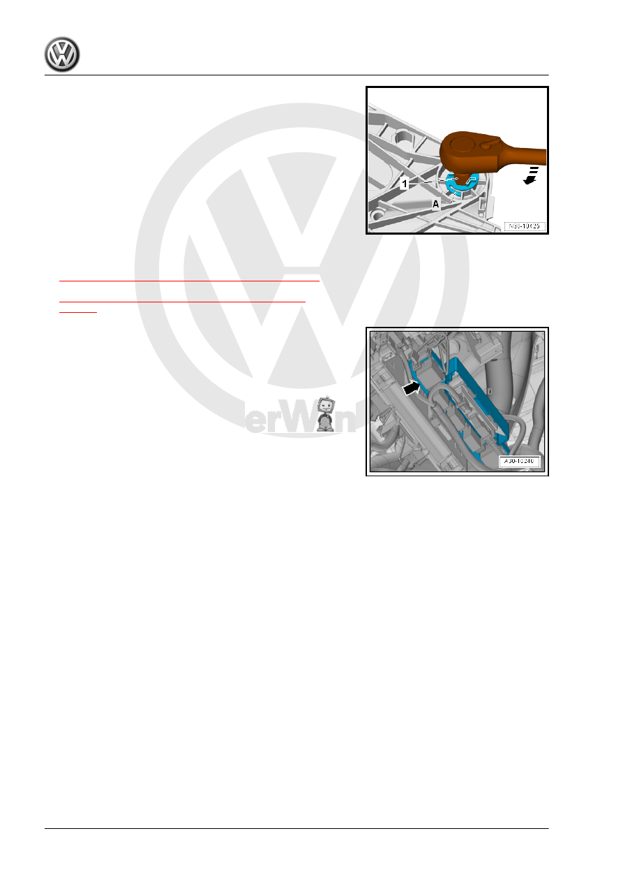
Install in reverse order of removal. Note the following:
Item -1- is a 14 mm internal socket wrench
A 14 mm hex socket wrench can also be used instead of a 14 mm
internal socket wrench.
• Replace bearing axle after removing.
– Press on the clutch pedal a little and push the new bearing
axle through all the way.
– Turn the bearing axle all the way to the right, in the direction
of -arrow-.
• The retainers -A- must engage audibly.
– Install return spring in bracket. Refer to
⇒ “1.6 Return Spring, Removing and Installing”, page 24
, or
over-center spring in bracket. Refer to
⇒ “1.5 Over-Center Spring, Removing and Installing”,
.
– If removed: Install the bracket -arrow- with Parking Aid Control
Module - J446- . Refer to ⇒ Electrical Equipment; Rep. Gr.
94 ; Parking Aid; Overview - Parking Aid .
– Install the driver side footwell cover, if removed. Refer to ⇒
Body Interior; Rep. Gr. 68 ; Storage Compartments/Covers .
1.8
Mounting Bracket, Removing and Instal‐
ling
Special tools and workshop equipment required
♦ Sealing Tool - T10249-
♦ -T10249/1-
♦ Torque Wrench 1331 5-50Nm - VAG1331-
♦ Hose Clamps - Up To 25mm - 3094-
Removing
– Move the driver seat as far back as possible.
– Move the steering wheel upward as far as possible. Use the
entire steering column adjustment range.