Volkswagen Golf / Golf GTI / Golf Variant. Manual - part 488
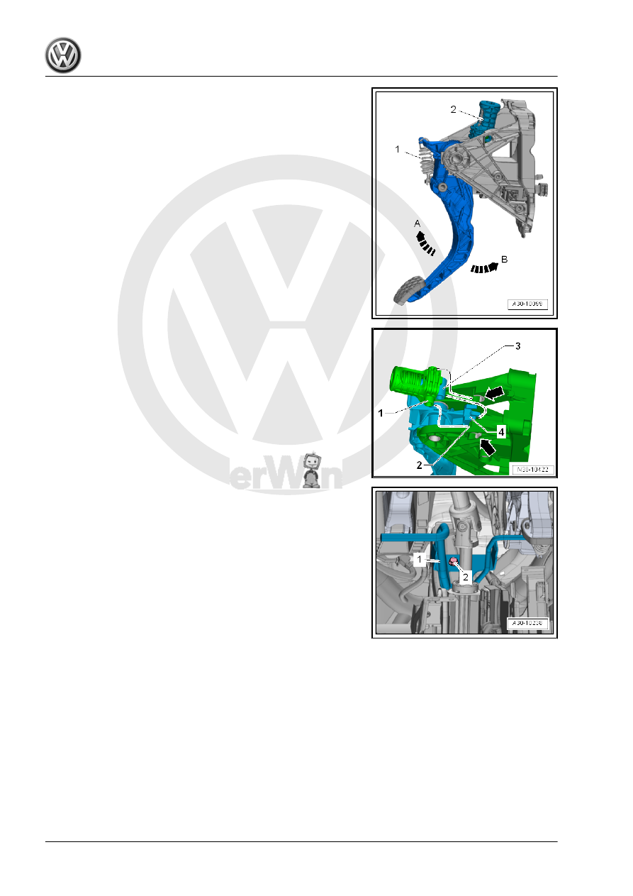
– If present, push the clutch pedal in the direction of -arrow B-
to disengage and remove the tension spring -1-.
– Bring clutch pedal to the rest position.
– Pull the clutch pedal in the direction of -arrow A- and disen‐
gage and remove the over-center spring -2-.
Installing
Install in reverse order of removal. Note the following:
• The bearing shells -arrows- for the pins -1- are installed.
– Pull the clutch pedal into the passenger compartment in the
direction of -arrow A- (refer to the previous illustration).
– Fit the pins -1- into the bracket mounts -2-.
– Fit the mounting -3- into the clutch pedal mount -4-.
• If the clutch pedal is pushed in the direction of -arrow B- (refer
to the previous illustration), the over-center spring will fold in
the direction of the bracket.
– Use a new mounting pin to connect the valve fitter/clutch mas‐
ter cylinder to the clutch pedal.
– Insert the crash bolster -1- and tighten the bolt -2-. Refer to ⇒
Body Interior; Rep. Gr. 70 ; Instrument Panel; Overview - In‐
strument Panel .
– Install the Data Bus on Board Diagnostic Interface - J533- .
Refer to ⇒ Electrical Equipment; Rep. Gr. 97 ; Control Mod‐
ules; Component Location Overview - Control Modules .
– Install the driver side footwell vent. Refer to ⇒ Heating, Ven‐
tilation and Air Conditioning; Rep. Gr. 87 ; Air Routing; Driver
Side Footwell Vent, Removing and Installing .
Vehicles with a Knee Airbag
– Install the driver side knee airbag. Refer to ⇒ Body Interior;
Rep. Gr. 69 ; Knee Airbags; Overview - Knee Airbag .
Vehicles without Knee Airbag
– Connect the battery. Refer to ⇒ Electrical Equipment; Rep.
Gr. 27 ; Battery; Battery, Disconnecting and Connecting .
1.6
Return Spring, Removing and Installing
Removing
– Move the driver seat as far back as possible.
– Move the steering wheel upward as far as possible. Use the
entire steering column adjustment range.