Volkswagen Golf / Golf GTI / Golf Variant. Manual - part 434


  Index      Volkswagen     Volkswagen Golf / Golf GTI / Golf Variant - service repair manual 2013 year


Search            copyright infringement  


Content   ..  432  433  434  435   ..


Volkswagen Golf / Golf GTI / Golf Variant. Manual - part 434


Installing
Install in reverse order of removal while paying attention to the

following:
– Check body openings -arrow- for deformations.
– In the case of deformation, readjust the panel with a plastic

hammer.

Note

Remaining minor deformation is permissible.

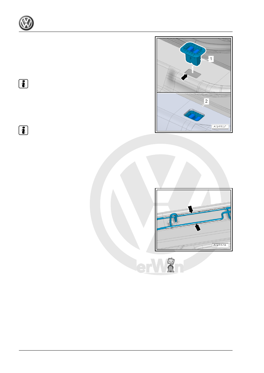
– Lift the carpet -2- and press in new mounting grommets -1-

until they engage audibly in body opening -arrow-.

– Place the carpet around the grommet as illustrated.

Note

The carpet must not cover the grommet.

– Check if the wire frame is aligned in the marked area

-arrows- before installing the rear bench seat.

– If the wire frame is bent, bend it back far enough until it is re‐

aligned.

– Install the rear bench seat and push the wire hooks into the

mounting grommets.

– Make sure the wire hooks are engaged correctly in the grom‐

mets.

3.8

Rear Seat Backrest, Removing and In‐

stalling

Special tools and workshop equipment required
♦ Torque Wrench 1331 5-50Nm - VAG1331-

Removing
– Remove the rear bench seat. Refer to

⇒ “3.7 Bench Seat/Single Seat, Removing and Installing”,

page 382

 .

– Remove the seat belt latch with the right rear belt end fitting.

Refer to

⇒ “1.15 Rear Seat Belt Latch, Removing and Installing”, page

121

 .

– Remove the cover -1- from the center support -2-.
– Remove the bolt -2-.
– Equipment levels with pass-through: open the pass through

door, and fold forward.

– Fold the rear securing clip -1- in direction of -arrow A-, disen‐

gage at the front from the center support -arrow B- and re‐

move.

Note

To improve clarity, the left rear seat backrest 1/3 is not shown.

– Lift the rear seat backrest -2- out of the center support -3- and

pull it out toward the center of the vehicle out of its outer

mounts -1- -arrows-.

– Remove rear seat backrest from the vehicle.
Installing
– In a vertical installation position, slide the rear seat backrest

-2- onto the outer mounting pins -1-.

– Place the rear seat backrest -2- in the center support -3-.

Installation is performed in reverse order of the removal.
Tightening Specifications
♦ Refer to 

⇒ “3.2 Overview - Rear Seat Backrest”, page 377

3.9

Locking Mechanism Trim, Removing

and Installing

Special tools and workshop equipment required
♦ Trim Removal Wedge - 3409-
♦ Hook - T10538-
Removing

Note

Due to the limited amount of space near the “locking mechanism

trim”, it is helpful to work with a second technician.

– Remove the respective rear headrest. Refer to

⇒ “3.14 Headrest, Removing and Installing”, page 390

 .

– Using a screwdriver, unhook the side and upper backrest cov‐

er molding strip near the trim from the backrest.

– Using the Trim Removal Wedge - 3409- , carefully push the

cover outward at the side of the trim -2-.

– Using a light, determine the position of the respective release

tab -1-.

– Carefully bend the respective release tab -1- outward using

the Hook - T10538- .

– After both release tabs -1- have been bent outward, pull the

trim upward in direction of -arrow- and remove.

Installing
Install in reverse order of removal while paying attention to the

following:
– After installing the trim, the rear seat backrest locking mech‐

anism must function easily.

3.10

Rear Seat Backrest Locking Mecha‐

nism, Removing and Installing

Special tools and workshop equipment required
♦ Torque Wrench 1331 5-50Nm - VAG1331-
Removing
– Remove the locking mechanism trim. Refer to

⇒ “3.9 Locking Mechanism Trim, Removing and Installing”,

page 386

 .

– Only loosen the cover in the locking mechanism area. Refer

to

⇒ “2.4 Rear Seat Backrest Cover and Cushion, Removing and

Installing”, page 419

 .

Wagon
– Remove the seat-side release cable from the locking mecha‐

nism -1-. Refer to 

⇒ page 395

 .

Continuation for All Vehicles
– Remove the bolts -2-.
– Remove the locking mechanism -1- from the backrest frame.
Installing
Install in reverse order of removal.
Tightening Specifications
♦ Refer to 

⇒ “3.3 Overview - Locking Mechanism”, page 379

3.11

Pass-Through Cover Frame, Removing

and Installing

Special tools and workshop equipment required
♦ Trim Removal Wedge - 3409-
♦ Trim Release Lever - T10039-
♦ Hook Tool - T40207-
Removing
– Fold down the center armrest and open the pass-through door.
– Unclip the trim -1- from the rear seat backrest using the Trim

Removal Wedge - 3409- -arrows-.

– Use the Hook Tool - T40207- to remove the retaining tabs

-2- alternating between the sides.

– Pry off the cover frame -2- using the Trim Release Lever -

T10039- from the rear seat backrest -1- in direction of

-arrow A-.

– Continue prying off starting at the upper left corner in direction

of -arrow B-.


Content   ..  432  433  434  435   ..