Volkswagen Golf / Golf GTI / Golf Variant. Manual - part 245


  Index      Volkswagen     Volkswagen Golf / Golf GTI / Golf Variant - service repair manual 2013 year


Search            copyright infringement  


Content   ..  243  244  245  246   ..


Volkswagen Golf / Golf GTI / Golf Variant. Manual - part 245


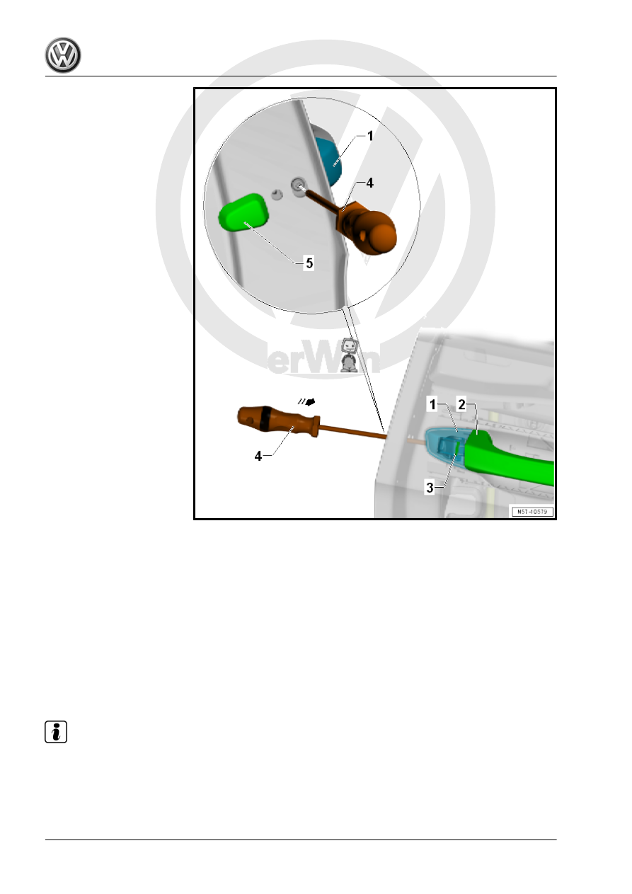
– Lightly push the cap -1- onto the door.
– Guide a screwdriver with a flat blade -4- approximately 40 mm

until the bracket locking hook -3-.

– Push the cap -1- onto the door.
– Push in the screwdriver approximately 5 mm -arrow-, until the

hook -3- locks.

– Secure the plug -5-.

2.10

Lock Cylinder, Removing and Installing

Special tools and workshop equipment required
♦ Torque Wrench 1783 - 2-10Nm - VAG1783-

Note

The following describes the removal and installation of a left lock cylinder. The right side is identical.

There can be different covers -4, 6, or 7- installed.

Removing

– Remove the lock cylinder cap. Refer to

⇒ “2.8 Lock Cylinder Cap, Removing and Installing”,

page 106

 .

– Lift off the covers -4 and 5- or -7-.
– Remove the bolt -5-.
– Remove the screw -8- all the way.
– Push in the screw -8- with the locking mechanism -9- in direc‐

tion of -arrow a-. Only then is the lock cylinder released.

– Remove the door handle -2- from the door.
– Remove the lock cylinder housing -1- from the bracket -3- at

a right angle in direction of -arrow b- to the door.

Installing

– Pull out on the door handle -2- from the door.
– Install the lock cylinder housing -1- into the bracket -3- at a

right angle in direction of -arrow a-.

– Install the bolts -5 and 8- into the mounting bracket. The bolt

-8- draws the locking mechanism -9- into position in direction

of -arrow b-.

Note

The lock cylinder housing must be pressed onto the outer door panel while installing.

Installation is performed in reverse order of the removal.
Tightening Specifications

2.11

Door Handle, Removing and Installing

Note

The following describes the removal and installation of the right door handle. The left side is identical.

Removing

For notes and procedures regarding a door handle with the key‐

less access authorization system. Refer to ⇒  Electrical Equip‐

ment; Rep. Gr.  94 ; Access/Start Authorization .
– Depending on the version, remove the lock cylinder cap and

the lock cylinder. Refer to

⇒ “2.8 Lock Cylinder Cap, Removing and Installing”,

page 106

 and

⇒ “2.10 Lock Cylinder, Removing and Installing”, page 112

 .

– Or remove the cap without the lock cylinder. Refer to

⇒ “2.9 Cap without Lock Cylinder, Removing and Installing”,

page 108

 .

– Pull the door handle -1- slightly to the rear in direction of

-arrow a- and out of the bracket mount.

– Pivot the door handle in the direction of -arrow b-.
– Remove the door handle at a right angle in direction of

-arrow c- from the bracket.

For vehicles with a keyless access authorization system, the con‐

nector is loosened when removing the door handle.
Installing


Content   ..  243  244  245  246   ..