Volkswagen Golf / Golf GTI / Golf Variant. Manual - part 246


  Index      Volkswagen     Volkswagen Golf / Golf GTI / Golf Variant - service repair manual 2013 year


Search            copyright infringement  


Content   ..  244  245  246  247   ..


Volkswagen Golf / Golf GTI / Golf Variant. Manual - part 246


For notes and procedures regarding a door handle with the key‐

less access authorization system. Refer to ⇒  Electrical Equip‐

ment; Rep. Gr.  94 ; Access/Start Authorization .
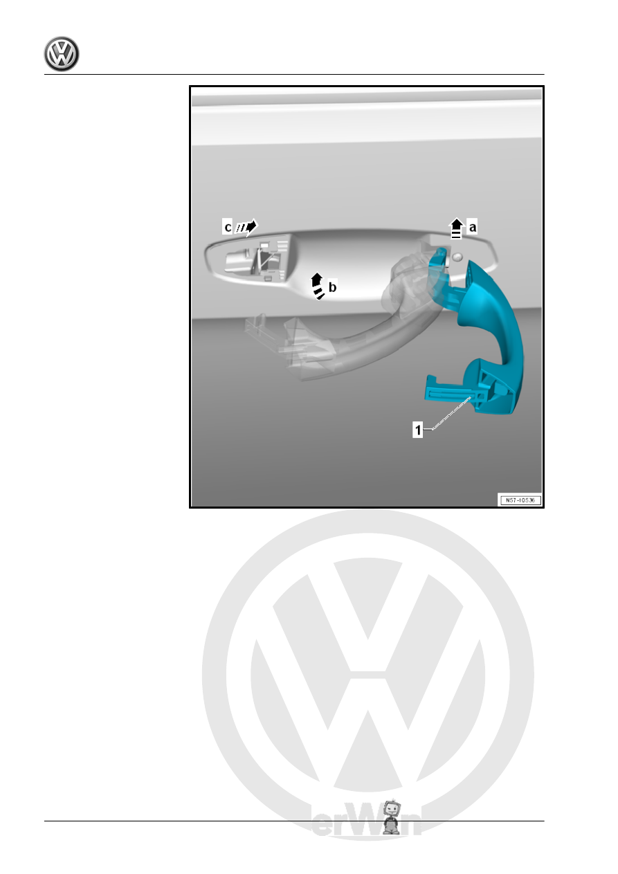
– Insert the door handle -1- into the bracket at a right angle in

direction of -arrow a-.

For vehicles with a keyless access authorization system, the con‐

nector is brought together when installing the door handle.
– Pivot the door handle -1- into the door in direction of

-arrow b-.

– Push the door handle toward the front in direction of

-arrow c- into the mount in the bracket.

– Always perform a function test with the door open.

2.12

Bracket, Removing and Installing

Special tools and workshop equipment required
♦ Torque Wrench 1783 - 2-10Nm - VAG1783-

Note

The following describes the removal and installation of the left bracket. The right side is identical.

Removing

– Remove the front door trim panel. Refer to ⇒  Body Interior;

Rep. Gr.  70 ; Front Door Trim Panels; Front Door Trim Panel,

Removing and Installing .

– Depending on the version, remove the lock cylinder cap and

the lock cylinder. Refer to

⇒ “2.8 Lock Cylinder Cap, Removing and Installing”,

page 106

 and

⇒ “2.10 Lock Cylinder, Removing and Installing”, page 112

 .

– Or remove the cap without the lock cylinder. Refer to

⇒ “2.9 Cap without Lock Cylinder, Removing and Installing”,

page 108

 .

– Remove the door handle. Refer to

⇒ “2.11 Door Handle, Removing and Installing”, page 114

 .

– Remove the door inner cover. Refer to

⇒ “2.6 Door Inner Cover, Removing and Installing”,

page 104

 .

– Remove the bolt -4- and remove the backing plate -3-.
– Remove the bracket -1- from the front door in direction of

-arrow d-.

Detach the Release Cable.
– Release the retainer -5- and pivot it out of the mount in the

bracket in direction of -arrow a-.

– Remove the pin for the release cable from the mount in direc‐

tion of -arrow b-.

– Remove the release cable -2- from the bracket -1- in direction

of -arrow c-.

Installing

Securing the Release Cable
– Guide the release cable -2- in the bracket -1-.
– Install the release cable bolts in the mount in direction of

-arrow b-.

– Pivot the retainer -5- into the mount in the bracket in direction

of -arrow c- and engage.

– Guide the bracket -1- into the front door in direction of

-arrow a-.

– Install the backing plate -3- and tighten the screw -4-.
Installation is performed in reverse order of the removal.
Tightening Specifications

2.13

Door Lock, Removing and Installing

Special tools and workshop equipment required
♦ Torque Wrench 1331 5-50Nm - VAG1331-
♦ Cylinder Head Bolt Socket - 3410-

Note

The following describes the removal and installation of the left door lock. The right side is identical.

The door window must be closed for the following work procedures.

Removing


Content   ..  244  245  246  247   ..