Volkswagen Golf / Golf GTI / Golf Variant. Manual - part 211
Test Procedure
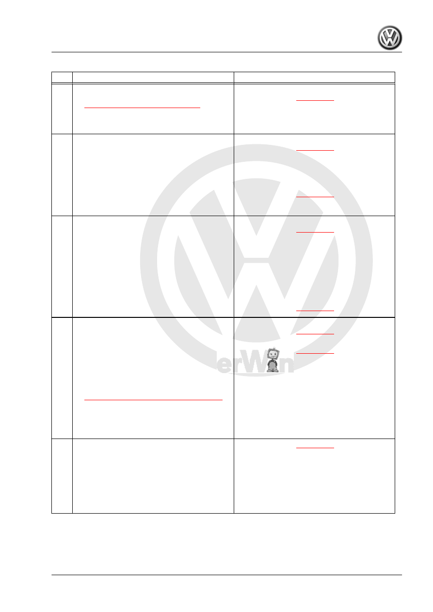
Step
Procedure
Result / Action to Take
1
• PERFORM: Preliminary Check to verify the
customers complaint. Refer to
⇒ “3.1 Preliminary Check ”, page 18
– Was Complaint verified?
– YES:
– NO:
♦ GATHER more information from customer
about the complaint.
2
• IGNITION: OFF.
• DISCONNECT: Oxygen Sensor 1 Before Cat‐
alytic Converter - GX10- harness connector.
• CHECK: Oxygen Sensor 1 Before Catalytic
Converter - GX10- component connector ter‐
minals 3 to 4 for resistance.
• SPECIFIED VALUE: 2 - 4 Ω ( @ 25° C).
– Was Value obtained?
– YES:
– NO:
♦ REPLACE: Oxygen Sensor 1 Before Catalytic
Converter - GX10- . Refer to appropriate repair
manual.
3
• IGNITION: ON.
• CHECK: Oxygen Sensor 1 Before Catalytic
Converter - GX10- harness connector terminal
4 to ground for voltage.
• IGNITION: OFF.
• SPECIFIED VALUE: Battery voltage.
– Was Value obtained?
– YES:
– NO:
♦ PERFORM: Visual Inspection of wiring and
component.
♦ CHECK: Wiring for open, high resistance,
short or harness connector for damage, corro‐
sion, loose or broken terminals.
♦ REPAIR: Faulty wiring or connector.
♦ GO TO: Step 7
4
• RECONNECT: Oxygen Sensor 1 Before Cat‐
alytic Converter - GX10- harness connector.
• CONNECT: Scan Tool.
• START: Engine and let Idle.
• Perform the function test located in diagnostic
mode 06. Refer to appropriate Diagnostic
Mode 06 - Read Test Results for Specific Di‐
agnostic Functions,
⇒ “3.3 Diagnostic Modes 01 - 0A”, page 21
• SPECIFIED VALUE: Mode 6 Pass.
• IGNITION: OFF.
– Were Values obtained?
– YES:
– NO:
5
• FAULT: Is intermittent.
• PERFORM: Visual Inspection of wiring and
component.
• CHECK: Wiring for open, high resistance,
short or harness connector for damage, corro‐
sion, loose or broken terminals.
• REPAIR: Faulty wiring or connector.
GTI 2014 ➤
Generic Scan Tool - Edition 04.2015
3. Diagnosis and Testing
517