Content .. 2724 2725 2726 2727 ..
Toyota Tundra (2015 year). Manual - part 2726
A
B
GO TO STEP 17
16.
CHECK FOR OPEN IN ONE SIDE OF CAN BRANCH WIRE (BRAKE CONTROL WITH
BRACKET RELAY CAN BRANCH WIRE)
(a) Disconnect the cable from the negative (-) battery terminal
Wait at least 90 seconds after disconnecting the cable from the
negative (-) battery terminal to disable the SRS system.
NOTICE:
When disconnecting the cable, some systems need to be
initialized after the cable is reconnected
.
(b) Measure the resistance according to the value(s) in the table below.
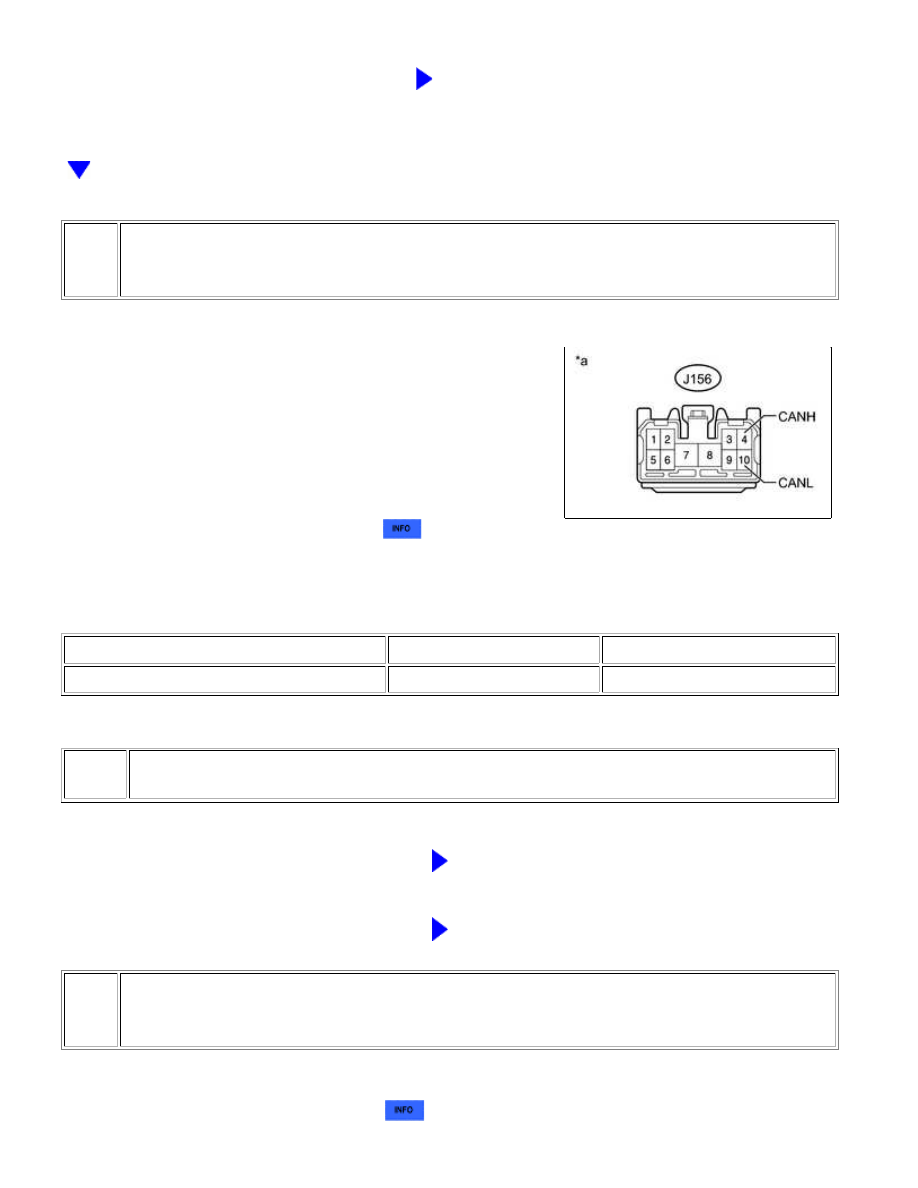
Standard Resistance:
TESTER CONNECTION
SWITCH CONDITION
SPECIFIED CONDITION
J156-4 (CANH) - J156-10 (CANL)
Ignition switch off
54 to 69 Ω
Text in Illustration
*a
NG
REPAIR OR REPLACE CAN BRANCH WIRE OR
CONNECTOR (BRAKE CONTROL WITH BRACKET
RELAY)
OK
REPLACE BRAKE CONTROL WITH BRACKET RELAY
17.
CHECK FOR OPEN IN ONE SIDE OF CAN BRANCH WIRE (AIR CONDITIONING
AMPLIFIER ASSEMBLY)
(a) Disconnect the J19 air conditioning amplifier assembly connector.
(b) Select "Bus Check" on the Techstream
.
CAN COMMUNICATION: CAN COMMUNICATION SYSTEM: Open i...