Content .. 2701 2702 2703 2704 ..
Toyota Tundra (2015 year). Manual - part 2703
Last Modified: 9-16-2014
6.6 J
Doc ID: RM000002VTJ00SX
Model Year: 2015
Model: Tundra
Prod Date Range: [08/2014 - ]
Title: CAN COMMUNICATION: CAN COMMUNICATION SYSTEM: 4WD Control ECU Communication Stop Mode;
2015 MY Tundra [08/2014 - ]
4WD Control ECU Communication Stop Mode
DESCRIPTION
DETECTION ITEM
SYMPTOM
TROUBLE AREA
4WD Control ECU
Communication Stop
Mode
Either condition is met:
"Four Wheel Drive Control" is not
displayed on the "Bus Check" screen.
"4WD Control ECU Communication Stop
Mode" in "DTC Combination Table"
applies.
Power source or inside
4WD control ECU
4WD control ECU CAN
branch wire or
connector
4WD control ECU
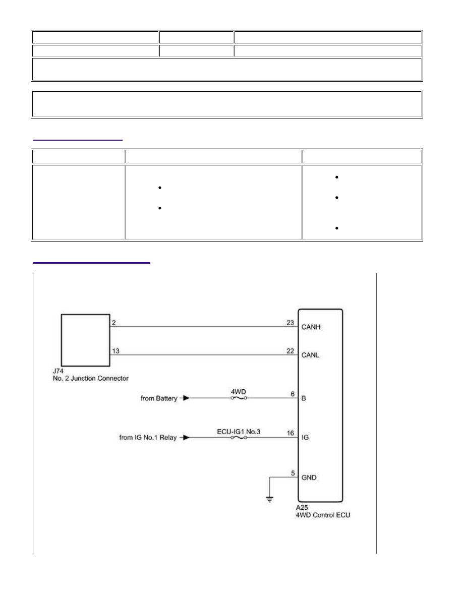
WIRING DIAGRAM
CAN COMMUNICATION: CAN COMMUNICATION SYSTEM: 4WD C...