Content .. 2700 2701 2702 2703 ..
Toyota Tundra (2015 year). Manual - part 2702
Last Modified: 9-16-2014
6.6 J
Doc ID: RM000002VTF00RX
Model Year: 2015
Model: Tundra
Prod Date Range: [08/2014 - ]
Title: CAN COMMUNICATION: CAN COMMUNICATION SYSTEM: Center Airbag Sensor Communication Stop Mode;
2015 MY Tundra [08/2014 - ]
Center Airbag Sensor Communication Stop Mode
DESCRIPTION
DETECTION ITEM
SYMPTOM
TROUBLE AREA
Center Airbag Sensor
Communication Stop
Mode
Either condition is met:
"Airbag" is not displayed on the "Bus
Check" screen.
"Center Airbag Sensor
Communication Stop Mode" in "DTC
Combination Table" applies.
Power source or center
airbag sensor assembly
Center airbag sensor
assembly CAN branch
wire or connector
Center airbag sensor
assembly
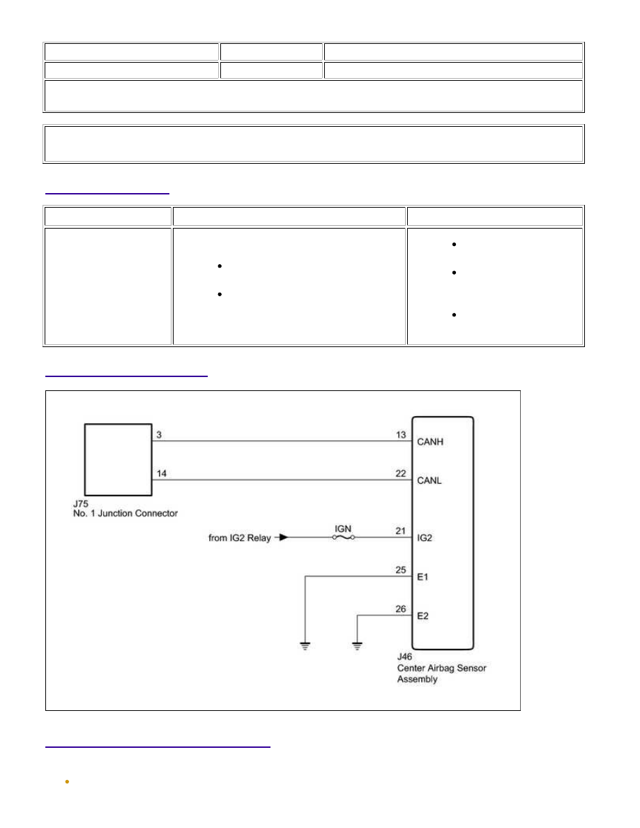
WIRING DIAGRAM
INSPECTION PROCEDURE
NOTICE:
The vehicle is equipped with an SRS (Supplemental Restraint System) which includes components such as
CAN COMMUNICATION: CAN COMMUNICATION SYSTEM: Center ...