Toyota Tundra (2015 year). Manual - part 250


  Index      Toyota     Toyota Tundra (2015 year) - Service and Repair Manual


Search            copyright infringement  


Content   ..  248  249  250  251   ..


Toyota Tundra (2015 year). Manual - part 250


OK

(a) Disconnect A18 booster connector.

(b) Turn the ignition switch to ON.

(c) Measure the voltage according to the value(s) in the table below.

Standard Voltage:

TESTER CONNECTION

SWITCH CONDITION

SPECIFIED CONDITION

A18-5 (STS) - Body ground

Ignition switch ON

4.3 to 6.3 V

NG

GO TO STEP 3

2.

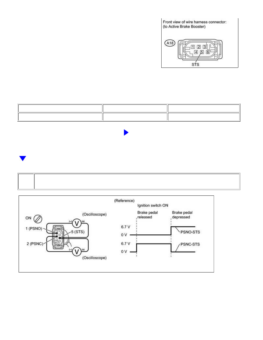
CHECK BOOSTER PEDAL MICRO SWITCH

(a) When using an oscilloscope:

(2) Turn the ignition switch to ON.

(3) Check the signal waveform while the brake pedal is depressed and released.

BRAKE CONTROL: VEHICLE STABILITY CONTROL SYSTEM: C...

OK

OK:

Signal waveform changes as shown in the illustration.

(b) When not using an oscilloscope:

(1) Disconnect the A18 booster connector.

(2) Turn the ignition switch to ON.

(3) Measure the voltage according to the value(s) in the table

below.

Standard Voltage:

TESTER CONNECTION

CONDITION

SPECIFIED

CONDITION

A18-2 (PSNC) - A18-5

(STS)

Brake pedal is

depressed

6 V

A18-1 (PSNO) - A18-5

(STS)

Brake pedal is

released

NG

REPLACE BRAKE BOOSTER ASSEMBLY

3.

CHECK HARNESS AND CONNECTOR (BOOSTER PEDAL MICRO SWITCH - SKID CONTROL
ECU)

(a) Confirm that the skid control ECU connector and brake

booster connector are properly connected.

BRAKE CONTROL: VEHICLE STABILITY CONTROL SYSTEM: C...

(b) Disconnect the A17 ECU connector.

(c) Disconnect the A18 booster connector.

(d) Inspect both the connector case and the terminal for deformation and corrosion.

OK:

No deformation or corrosion.

(e) Measure the resistance according to the value(s) in the table below.

Standard Resistance:

TESTER CONNECTION

CONDITION

SPECIFIED CONDITION

A17-23 (PSNC) - A18-2 (PSNC)

Always

Below 1 Ω

A17-23 (PSNC) - Body ground

Always

10 kΩ or higher

A17-24 (PSNO) - A18-1 (PSNO)

Always

Below 1 Ω

A17-24 (PSNO) - Body ground

Always

10 kΩ or higher

A17-21 (STS) - A18-5 (STS)

Always

Below 1 Ω

A17-21 (STS) - Body ground

Always

10 kΩ or higher

NG

REPAIR OR REPLACE HARNESS OR CONNECTOR

OK

REPLACE VSC ACTUATOR ASSEMBLY

BRAKE CONTROL: VEHICLE STABILITY CONTROL SYSTEM: C...

NEXT

Last Modified: 9-16-2014

6.6 C

Doc ID: RM0000028P800YX

Model Year: 2015

Model: Tundra

Prod Date Range: [08/2014 -           ]

Title: BRAKE CONTROL: VEHICLE STABILITY CONTROL SYSTEM: C1290/66; Steering Angle Sensor Zero Point

Malfunction; 2015 MY Tundra [08/2014 -        ]

DTC

C1290/66 Steering Angle Sensor Zero Point Malfunction

DESCRIPTION

DTC

CODE

DTC DETECTION CONDITION

TROUBLE AREA

C1290/66

Steering angle sensor zero point deviates from zero point stored

in skid control ECU by 20 degrees or more.

Steering angle sensor

Steering angle sensor

circuit

CAN communication

system

WIRING DIAGRAM

Refer to C1231/31 


.

INSPECTION PROCEDURE

NOTICE:

When replacing the VSC actuator assembly, perform zero point calibration 


.

PROCEDURE

1.

DISCONNECT BATTERY NEGATIVE TERMINAL

(a) Disconnect the battery negative terminal to clear the steering angle sensor zero point.

2.

PERFORM STEERING ANGLE SENSOR ZERO POINT CALIBRATION

(a) Drive the vehicle straight ahead at 15 km/h (9 mph) or more for a few seconds (zero point is

obtained automatically).

BRAKE CONTROL: VEHICLE STABILITY CONTROL SYSTEM: C...


Content   ..  248  249  250  251   ..