Toyota Tundra (2015 year). Manual - part 248
OK
TESTER CONNECTION
CONDITION
SPECIFIED CONDITION
3 - 4
When battery voltage is not applied to terminals 1 and 2
Below 1 Ω
3 - 5
When battery voltage is not applied to terminals 1 and 2
10 kΩ or higher
3 - 4
When battery voltage is applied to terminals 1 and 2
10 kΩ or higher
3 - 5
When battery voltage is applied to terminals 1 and 2
Below 1 Ω
TESTER CONNECTION
CONDITION
SPECIFIED CONDITION
3 - 4
When battery voltage is not applied to terminals 1 and 2
Below 1 Ω
When battery voltage is applied to terminals 1 and 2
10 kΩ or higher
NG
REPLACE STOP LIGHT CONTROL RELAY
3.
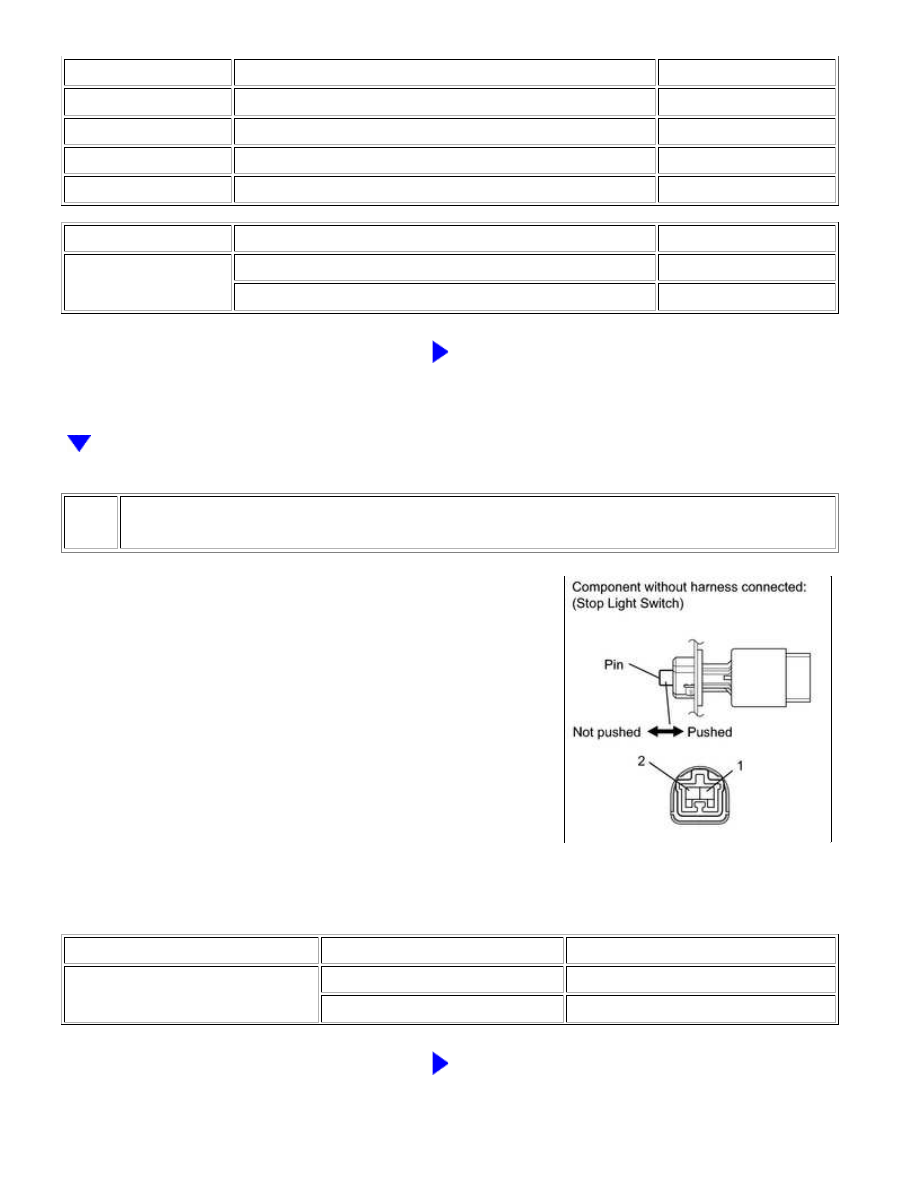
INSPECT STOP LIGHT SWITCH ASSEMBLY
(a) Disconnect the A4 switch connector.
(b) Measure the resistance according to the value(s) in the table below.
Standard Resistance:
TESTER CONNECTION
SWITCH CONDITION
SPECIFIED CONDITION
1 - 2
Pin not pushed
Below 1 Ω
Pin pushed
10 kΩ or higher
NG
REPLACE STOP LIGHT SWITCH ASSEMBLY
BRAKE CONTROL: VEHICLE STABILITY CONTROL SYSTEM: C...