Content .. 2263 2264 2265 2266 ..
Toyota Tundra (2015 year). Manual - part 2265
Last Modified: 9-16-2014
6.6 J
Doc ID: RM000002VXQ01HX
Model Year: 2015
Model: Tundra
Prod Date Range: [08/2014 - ]
Title: AIR CONDITIONING: AIR CONDITIONING SYSTEM (for Automatic Air Conditioning System): Air
Conditioning Compressor Magnetic Clutch Circuit; 2015 MY Tundra [08/2014 - ]
Air Conditioning Compressor Magnetic Clutch Circuit
DESCRIPTION
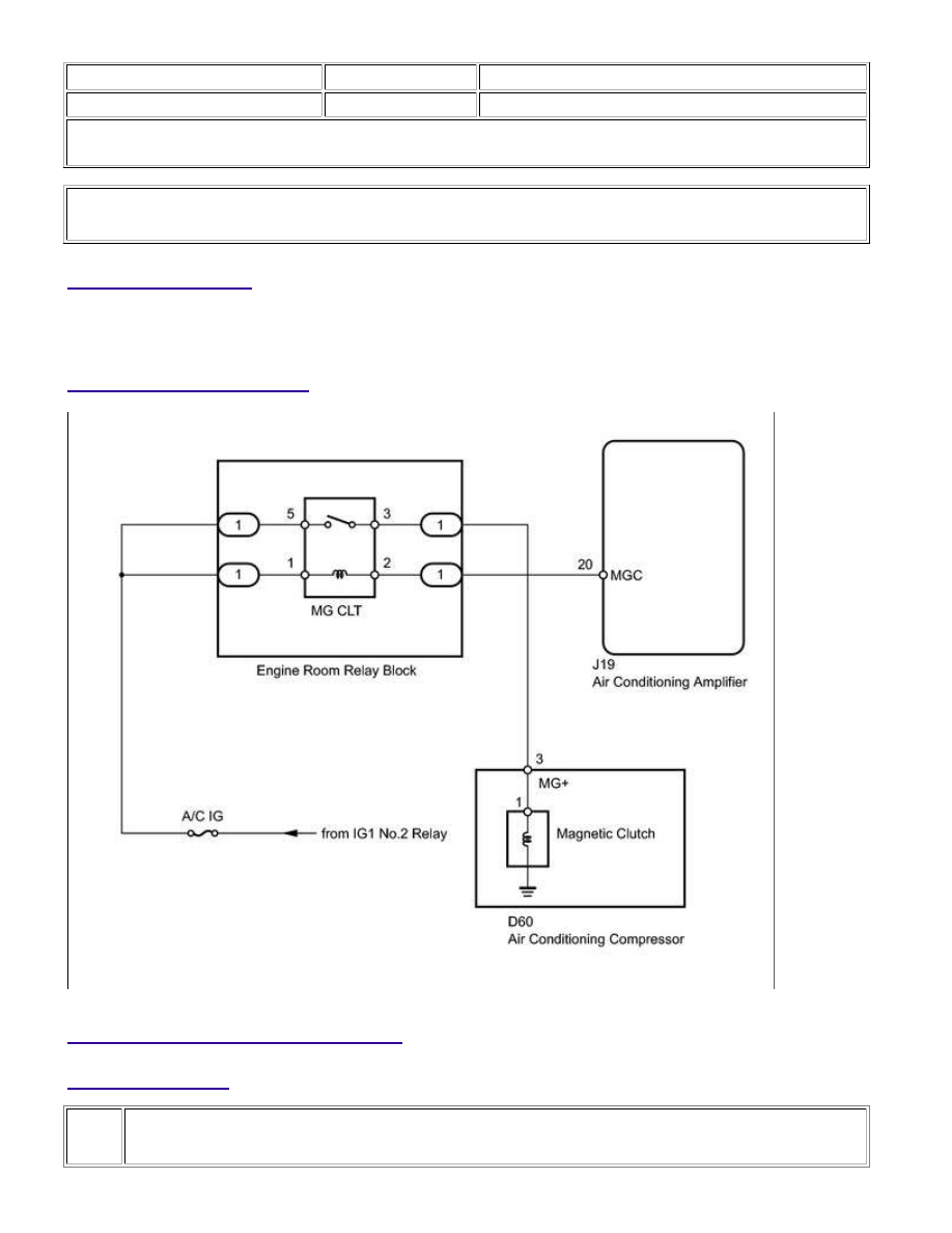
WIRING DIAGRAM
INSPECTION PROCEDURE
PROCEDURE
1.
READ VALUE USING TECHSTREAM (A/C SIGNAL)
AIR CONDITIONING: AIR CONDITIONING SYSTEM (for Automatic A...