Toyota Tundra (2015 year). Manual - part 2264


  Index      Toyota     Toyota Tundra (2015 year) - Service and Repair Manual


Search            copyright infringement  


Content   ..  2262  2263  2264  2265   ..


Toyota Tundra (2015 year). Manual - part 2264


OK

OK

2.

INSPECT FUSE (HTR)

(a) Remove the HTR H-fuse from the engine room relay block.

(b) Measure the resistance according to the value(s) in the table below.

Standard resistance:

TESTER CONNECTION

CONDITION

SPECIFIED CONDITION

HTR H-fuse

Always

Below 1 Ω

NG

REPLACE FUSE

3.

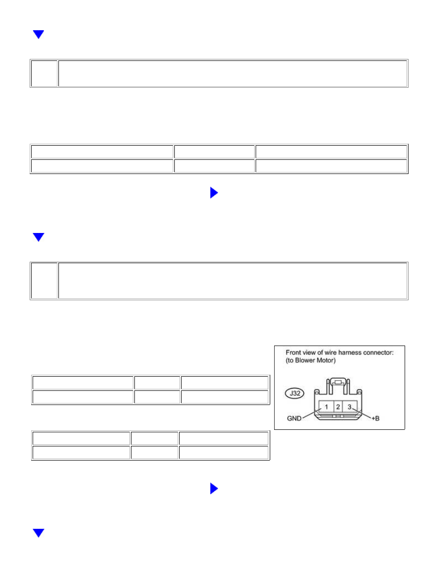
CHECK HARNESS AND CONNECTOR (BLOWER MOTOR - BATTERY AND BODY
GROUND)

(a) Disconnect the J32 blower motor connector.

(b) Measure the resistance and voltage according to the

value(s) in the table below.

Standard resistance:

TESTER CONNECTION

CONDITION

SPECIFIED CONDITION

J32-1 (GND) - Body ground

Always

Below 1 Ω

Standard voltage:

TESTER CONNECTION

CONDITION

SPECIFIED CONDITION

J32-3 (+B) - Body ground

Always

11 to 14 V

NG

REPAIR OR REPLACE HARNESS OR CONNECTOR

AIR CONDITIONING: AIR CONDITIONING SYSTEM (for Automatic A...

OK

4.

CHECK HARNESS AND CONNECTOR (AIR CONDITIONING AMPLIFIER - BLOWER
MOTOR)

(a) Disconnect the J19 air conditioning amplifier connector.

(b) Disconnect the J32 blower motor connector.

(c) Measure the resistance according to the value(s) in the table

below.

Standard resistance:

TESTER CONNECTION

CONDITION

SPECIFIED

CONDITION

J19-23 (BLW) - J32-2 (S1)

Always

Below 1 Ω

J19-23 (BLW) or J32-2 (S1) - Body

ground

Always

10 kΩ or higher

NG

REPAIR OR REPLACE HARNESS OR CONNECTOR

5.

CHECK BLOWER MOTOR (S1 VOLTAGE)

AIR CONDITIONING: AIR CONDITIONING SYSTEM (for Automatic A...

OK

(a) Disconnect the J19 air conditioning amplifier connector.

(b) Reconnect the J32 blower motor connector.

(c) Measure the voltage according to the value(s) in the table

below.

Standard voltage:

TESTER CONNECTION

SWITCH

CONDITION

SPECIFIED

CONDITION

J19-23 (BLW) - Body

ground

Ignition switch ON

4.5 to 5.5 V

NG

REPLACE BLOWER MOTOR

6.

CHECK AIR CONDITIONING AMPLIFIER (BLW VOLTAGE)

(a) Remove the air conditioning amplifier with its connectors

still connected 


.

(b) Turn the ignition switch ON.

(c) Turn the blower switch LO.

(d) Using an oscilloscope, check the waveform.

Standard:

TESTER

CONNECTION

TOOL SETTING

SWITCH

CONDITION

SPECIFIED

CONDITION

J19-23 (BLW) -

J19-14 (GND)

1 V/DIV., 500

µsec./DIV.

Ignition switch

ON

Blower switch

LO

Pulse

generation

HINT:

Waveform varies with the blower level.

AIR CONDITIONING: AIR CONDITIONING SYSTEM (for Automatic A...

NG

REPLACE AIR CONDITIONING AMPLIFIER

OK

PROCEED TO NEXT CIRCUIT INSPECTION SHOWN

IN PROBLEM SYMPTOMS TABLE

AIR CONDITIONING: AIR CONDITIONING SYSTEM (for Automatic A...


Content   ..  2262  2263  2264  2265   ..