Toyota Tundra (2015 year). Manual - part 2198


  Index      Toyota     Toyota Tundra (2015 year) - Service and Repair Manual


Search            copyright infringement  


Content   ..  2196  2197  2198  2199   ..


Toyota Tundra (2015 year). Manual - part 2198


OK

3.

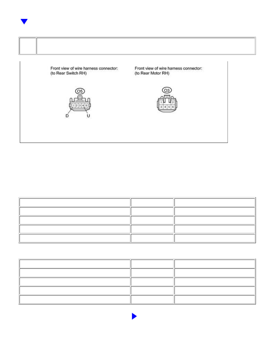
CHECK HARNESS AND CONNECTOR (REAR SWITCH RH - REAR MOTOR RH)

(a) Disconnect the O5 switch connector.

(b) Disconnect the O3 motor connector.

(c) Measure the resistance according to the value(s) in the table below.

Standard Resistance:

for Double Cab:

TESTER CONNECTION

CONDITION

SPECIFIED CONDITION

O5-1 (D) - O3-2

Always

Below 1 Ω

O5-4 (U) - O3-1

Always

Below 1 Ω

O5-1 (D) or O3-2 - Body ground

Always

10 kΩ or higher

O5-4 (U) or O3-1 - Body ground

Always

10 kΩ or higher

for CrewMax:

TESTER CONNECTION

CONDITION

SPECIFIED CONDITION

O5-1 (D) - O3-1

Always

Below 1 Ω

O5-4 (U) - O3-2

Always

Below 1 Ω

O5-1 (D) or O3-1 - Body ground

Always

10 kΩ or higher

O5-4 (U) or O3-2 - Body ground

Always

10 kΩ or higher

NG

REPAIR OR REPLACE HARNESS OR CONNECTOR

WINDSHIELD / WINDOWGLASS: POWER WINDOW CONTROL ...

OK

4.

INSPECT REAR POWER WINDOW REGULATOR MOTOR ASSEMBLY RH

(a) Remove the rear motor RH 


.

(b) Apply battery voltage to connector terminals 1 and 2.

(c) Check that the motor gear rotates smoothly as follows.

OK:

for Double Cab:

MEASUREMENT CONDITION

SPECIFIED CONDITION

Battery positive (+) → 1
Battery negative (-) → 2

Motor gear rotates counterclockwise

Battery positive (+) → 2
Battery negative (-) → 1

Motor gear rotates clockwise

for CrewMax:

MEASUREMENT CONDITION

SPECIFIED CONDITION

Battery positive (+) → 1
Battery negative (-) → 2

Motor gear rotates clockwise

Battery positive (+) → 2
Battery negative (-) → 1

Motor gear rotates counterclockwise

NG

REPLACE REAR POWER WINDOW REGULATOR

MOTOR ASSEMBLY RH

5.

CHECK HARNESS AND CONNECTOR (MASTER SWITCH - REAR SWITCH RH)

WINDSHIELD / WINDOWGLASS: POWER WINDOW CONTROL ...

OK

(a) Disconnect the N2 master switch connector.

(b) Disconnect the O5 switch connector.

(c) Measure the resistance according to the value(s) in the table below.

Standard Resistance:

TESTER CONNECTION

CONDITION

SPECIFIED CONDITION

N2-10 (U) - O5-5 (SU)

Always

Below 1 Ω

N2-18 (D) - O5-2 (SD)

Always

Below 1 Ω

N2-10 (U) or O5-5 (SU) - Body ground

Always

10 kΩ or higher

N2-18 (D) or O5-2 (SD) - Body ground

Always

10 kΩ or higher

NG

REPAIR OR REPLACE HARNESS OR CONNECTOR

6.

CHECK POWER WINDOW REGULATOR MASTER SWITCH ASSEMBLY

WINDSHIELD / WINDOWGLASS: POWER WINDOW CONTROL ...

(a) Remove the master switch 


.

(b) Reconnect the master switch connector.

(c) Measure the voltage according to the value(s) in the table

below.

Standard Voltage:

TESTER

CONNECTION

SWITCH CONDITION

SPECIFIED

CONDITION

N2-10 (U) -

N2-1 (E)

Ignition switch ON, rear RH

to 14 V

N2-18 (D) -

N2-1 (E)

Ignition switch ON, rear RH

REPLACE POWER WINDOW REGULATOR MASTER

SWITCH ASSEMBLY

OK

GO TO POWER WINDOWS DO NOT OPERATE AT

ALL

WINDSHIELD / WINDOWGLASS: POWER WINDOW CONTROL ...


Content   ..  2196  2197  2198  2199   ..