Content .. 2125 2126 2127 2128 ..
Toyota Tundra (2015 year). Manual - part 2127
A
1.
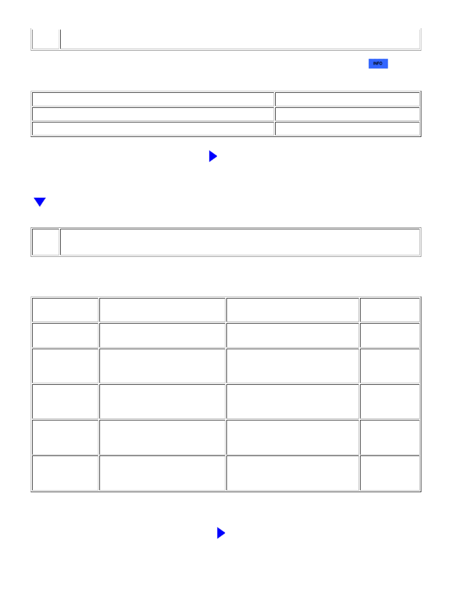
CHECK DTC
(a) Use the Techstream to check if the CAN communication system is functioning normally
.
Result
RESULT
PROCEED TO
CAN DTC is not output
A
CAN DTC is output
B
B
GO TO CAN COMMUNICATION SYSTEM
2.
READ VALUE USING TECHSTREAM (OUTER MIRROR SWITCH)
TESTER DISPLAY
MEASUREMENT ITEM/RANGE
NORMAL CONDITION
DIAGNOSTIC
NOTE
Mirror Selection
SW (Left)
Mirror master switch signal for LH
mirror / ON or OFF
ON: Switch is in L position
OFF: Switch is OFF or in R position
-
Mirror Position SW
(Right)
Mirror control switch signal
(RIGHT) / ON or OFF
ON: RIGHT switch is ON
OFF: Any switch except RIGHT is ON
or all switches are OFF
-
Mirror Position SW
(Left)
Mirror control switch signal (LEFT)
/ ON or OFF
ON: LEFT switch is ON
OFF: Any switch except LEFT is ON or
all switches are OFF
-
Mirror Position SW
(UP)
Mirror control switch signal (UP) /
ON or OFF
ON: UP switch is ON
OFF: Any switch except UP is ON or
all switches are OFF
-
Mirror Position SW
(Down)
Mirror control switch signal
(DOWN) / ON or OFF
ON: DOWN switch is ON
OFF: Any switch except DOWN is ON
or all switches are OFF
-
OK:
On screen, each item changes between ON and OFF according to above chart.
NG
GO TO STEP 5
MIRROR: POWER MIRROR CONTROL SYSTEM (w/ Memory): Driv...