Content .. 2094 2095 2096 2097 ..
Toyota Tundra (2015 year). Manual - part 2096
TESTER CONNECTION
SWITCH CONDITION
SPECIFIED CONDITION
A30-2 - Body ground
Light control switch TAIL, front fog light switch ON
11 to 14 V
Light control switch TAIL, front fog light switch OFF
Below 1 V
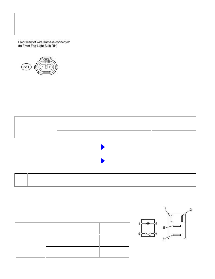
(b) for RH:
(1) Disconnect the A31 front fog light connector.
(2) Measure the voltage according to the value(s) in the table below.
Standard voltage:
TESTER CONNECTION
SWITCH CONDITION
SPECIFIED CONDITION
A31-2 - Body ground
Light control switch TAIL, front fog light switch ON
11 to 14 V
Light control switch TAIL, front fog light switch OFF
Below 1 V
NG
GO TO STEP 4
OK
REPAIR OR REPLACE HARNESS OR CONNECTOR
(FRONT FOG LIGHT BULB - BODY GROUND)
4.
INSPECT FOG LIGHT RELAY (FOG)
(a) Remove the fog light relay from the engine room relay block.
(b) Measure the resistance according to the value(s) in the table
below.
Standard resistance:
TESTER
CONNECTION
CONDITION
SPECIFIED
CONDITION
3 - 5
When battery voltage is not
applied to terminals 1 and 2
10 kΩ or higher
When battery voltage is applied
to terminals 1 and 2
Below 1 Ω
LIGHTING: LIGHTING SYSTEM: Front Fog Light Circuit; 2015 MY ...