Toyota Tundra (2015 year). Manual - part 1939


  Index      Toyota     Toyota Tundra (2015 year) - Service and Repair Manual


Search            copyright infringement  


Content   ..  1937  1938  1939  1940   ..


Toyota Tundra (2015 year). Manual - part 1939


Enter the following menu items: Powertrain / Engine and ECT / Data List / Intake Air.

3. 

Clear DTCs (even if no DTCs are stored, perform the clear DTC operation).

4. 

Turn the ignition switch off and wait for at least 30 seconds.

5. 

Turn the ignition switch to ON and turn the Techstream on [A].

6. 

Enter the following menu items: Powertrain / Engine and ECT / Utility / Evaporative System Check

/ Automatic Mode.

7. 

After the Evaporative System Check is completed, check for All Readiness by entering the following

menus: Powertrain / Engine and ECT / Utility / All readiness.

8. 

Input the DTC: P0451, P0452 or P0453.

9. 

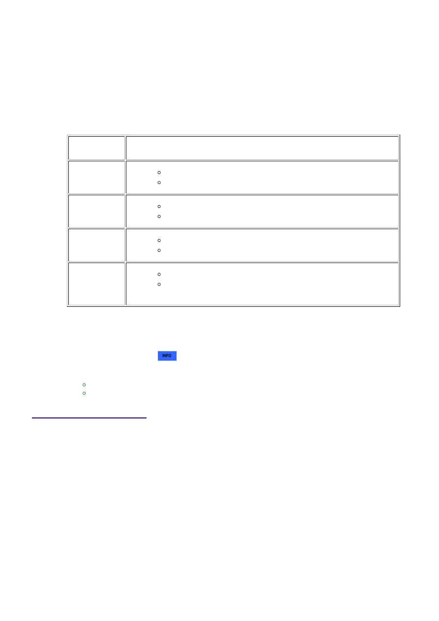
Check the DTC judgment result [B].

TESTER

DISPLAY

DESCRIPTION

NORMAL

DTC judgment completed

System normal

ABNORMAL

DTC judgment completed

System abnormal

INCOMPLETE

DTC judgment not completed

Perform driving pattern after confirming DTC enabling conditions

N/A

Unable to perform DTC judgment

HINT:

If the judgment result shows ABNORMAL, the system has a malfunction.

10. 

If the test result is INCOMPLETE or N/A and no pending DTC is output, perform a universal trip and

check for permanent DTCs 


.

HINT:

If a permanent DTC is output, the system is malfunctioning.
If no permanent DTC is output, the system is normal.

11. 

WIRING DIAGRAM

3UR-FE ENGINE CONTROL SYSTEM: SFI SYSTEM: P0451-P0453;...

INSPECTION PROCEDURE

NOTICE:

When a vehicle is brought into the workshop, leave it as it is. Do not change the vehicle condition. For
example, do not tighten the fuel cap.
Do not disassemble the canister pump module.
The Techstream is required to conduct the following diagnostic troubleshooting procedure.

PROCEDURE

1.

CONFIRM DTC AND EVAP PRESSURE

(a) Connect the Techstream to the DLC3.

(b) Turn the ignition switch to ON (do not start the engine).

(c) Turn the Techstream on.

3UR-FE ENGINE CONTROL SYSTEM: SFI SYSTEM: P0451-P0453;...

A

(d) Enter the following menus: Powertrain / Engine and ECT / Trouble Codes.

(e) Read DTCs.

(f) Enter the following menus: Powertrain / Engine and ECT / Data List / EVAP / Vapor Pressure

Pump.

(g) Read the EVAP (Evaporative Emission) pressure displayed on the Techstream.

Result

DISPLAY

(DTC

OUTPUT)

TEST RESULT

SUSPECTED TROUBLE AREA

PROCEED

TO

P0451

-

Canister pressure sensor

C

P0452

Less than 42.11009 kPa-a

(315.86779 mmHg-a)

Wire harness/connector (ECM -

Canister pressure sensor)

Canister pressure sensor

Short in ECM circuit

A

P0453

More than 123.76147 kPa-a

(928.33489 mmHg-a)

Wire harness/connector (ECM -

Canister pressure sensor)

Canister pressure sensor

Open in ECM circuit

B

B

GO TO STEP 4

C

GO TO EVAP SYSTEM

2.

CHECK HARNESS AND CONNECTOR (CANISTER PUMP MODULE - ECM)

(a) Turn the ignition switch off.

(b) Disconnect the D74 ECM connector.

(c) Measure the resistance according to the value(s) in the table below.

Result

TESTER

CONNECTION

CONDITION

SPECIFIED

CONDITION

SUSPECTED TROUBLE AREA

PROCEED

TO

D74-121 (PPMP) -

Body ground

Always

10 Ω or less

Wire harness/connector (ECM -

Canister pressure sensor)

Short in canister pressure sensor

circuit

A

3UR-FE ENGINE CONTROL SYSTEM: SFI SYSTEM: P0451-P0453;...

A

TESTER

CONNECTION

CONDITION

SPECIFIED

CONDITION

SUSPECTED TROUBLE AREA

PROCEED

TO

D74-121 (PPMP) -

Body ground

Always

10 kΩ or more

Wire harness/connector (ECM -

Canister pressure sensor)

Short in ECM circuit

B

B

GO TO STEP 8

3.

CHECK HARNESS AND CONNECTOR (CANISTER PUMP MODULE - ECM)

(a) Disconnect the R12 canister pump module connector.

(b) Disconnect the D74 ECM connector.

(c) Measure the resistance according to the value(s) in the table below.

Result

TESTER CONNECTION CONDITION

SPECIFIED

CONDITION

SUSPECTED TROUBLE AREA

PROCEED

TO

D74-121 (PPMP) -

Body ground

Always

10 kΩ or more

Short in canister pressure sensor circuit

A*1

B*2

D74-121 (PPMP) -

Body ground

Always

10 Ω or less

Short in wire harness/connector (ECM -

Canister pressure sensor)

C

HINT:

*1: for 100 L (26.4 US gal) Fuel Tank

*2: for 144 L (38 US gal) Fuel Tank

A

GO TO STEP 5

B

GO TO STEP 6

C

GO TO STEP 7

4.

CHECK HARNESS AND CONNECTOR (CANISTER PUMP MODULE - ECM)

(a) Disconnect the R12 canister pump module connector.

(b) Measure the resistance according to the value(s) in the table below.

Standard resistance:

3UR-FE ENGINE CONTROL SYSTEM: SFI SYSTEM: P0451-P0453;...


Content   ..  1937  1938  1939  1940   ..